EasyManua.ls Logo

Unitor UWI 500 TP - User Manual

Unitor UWI 500 TP
40 pages
Print Icon
To Next Page IconTo Next Page
Loading...
Revision date: 10/07/2017 Page 1 of 40
Instruction manual
Unitor Welding Inverter
UWI 500 TP & UWF 102
MMA, ACA, TIG and Wire welding

Questions and Answers

  • M
    Melissa ParsonsAug 8, 2025
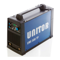
    What to do if Unitor UWI 500 TP has no output and yellow warning light is on?
    • L
      Larry MorrisAug 8, 2025
      If your Unitor Welding System shows no output and a yellow warning light, it could be due to several reasons. First, check the vessel's power supply for blown fuses or loose connections, as one phase might be missing. If the thermal protection is activated from overuse, allow the machine to cool down, then weld with more breaks or at a lower current. Ensure that the cooling airflow isn't blocked. Inspect electrode holder or ground cable connections for heat development due to looseness. Also, a broken fan may be the reason, so repair or replace it. Lastly, too much dirt in the power source compartment may cause this, so clean it.
  • T
    Thomas GarciaAug 14, 2025
    How to troubleshoot Unitor UWI 500 TP with no output, no warning light, and the fan not running?
    • K
      Kimberly BurkeAug 14, 2025
      If your Unitor Welding System has no output, no warning light, and the fan isn't running, the primary power isn't reaching the machine. Check the mains fuses, ensure the machine is plugged in, and inspect the primary cable for any breaks. Also, verify that the cable connection to the machine is secure, the machine is switched on, and the on/off switch isn't damaged. If the mains fuses are blown, replace them.
  • T
    Timothy BurnsAug 22, 2025
    Why is the arc unstable on my Unitor UWI 500 TP?
    • W
      wgardnerAug 22, 2025
      An unstable arc in your Unitor Welding System can occur due to several factors. Ensure the polarity on the machine matches the wire. Check the ground clamp and torch connections for poor contact. Also, make sure the workpiece is clean.
  • K
    Kimberly Scott DDSAug 29, 2025
    What to do if Unitor Welding System has no arc and no warning light?
    • R
      Ronald SmithAug 29, 2025
      If your Unitor Welding System has no arc and no warning light, it could be due to an incomplete circuit. Inspect the ground cable and torch connections.

Summary

1 General Description

2 Technical Data

Safety Markings

No-Load Voltage (Ur)

Defines no-load voltage and its safety implications, referencing Australian standards.

Arc Striking Voltage (Uo)

Explains arc striking voltage and its importance for easy arc starts.

Arc Voltage (U2)

Defines arc voltage and its relation to welding current for different modes.

Primary Connection Details

Cooling System Information

Protection Class (IP23 S)

Thermal Insulation Class (Class H)

EU Conformity and CE Marking

RoHS Directive Compliance

3 Installation Procedure

Machine Dimensions and Weight

Lists the physical dimensions and weight for UWI-500 and UWF-102 models.

Selecting a Suitable Location

Advises on selecting an appropriate dry location with good air circulation for the machine.

Avoiding Tilting the Machine

Specifies the requirement for placing the machine on a secure, level surface.

Rear Panel Functions and Connections

Primary Cable Connection

Details the primary cable connection and its associated fuse requirement.

On;Off Switch

Identifies the main power on/off switch for the equipment.

Total Protection Indicator Light

Explains the indicator for the Total Protection function, related to power supply issues.

Remote Control Connection Port

Describes the connection point for remote control devices.

Power Supply Transformer Fuse

Identifies the fuse for the power supply transformer.

Control Cable to Wire Feeder

Notes the connection for the control cable to the wire feeder.

4 Front Panel Controls Overview

Selecting the Welding Process

Explains how to select the welding process (MMA, CEL, ACA, TIG) using the front panel button.

Selecting Remote Control Mode

Details how to select front panel control or remote control for the machine.

Arc Force Adjustment

Explains the function and adjustment of the Arc Force control for welding characteristics.

Hot Start Functionality

Warning Lights and Display Messages

AL.H Display Message

Describes the AL.H display message indicating overheating and necessary actions.

E.69 Display Message

Explains the E.69 display message related to wire feeder software faults.

Display Settings and Selection

Select Current Display (A)

Describes how the display shows the set welding current when 'A' is selected.

Select Voltage Display (V)

Explains that the display shows no-load or arc voltage when 'V' is selected.

5 Stick Electrode Welding

Hot Start Adjustment

Explains the Hot Start setting and its effect on arc striking and electrode sticking.

Arc Force Adjustment

Details the Arc Force setting and its impact on arc characteristics for different electrode types.

6 Air Carbon Arc Gouging

7 TIG (GTAW) Welding

8 Wire Welding Operations

UWF-102 Front Panel Controls

Selecting Welding Process (UWF-102)

Explains how to select the welding process on the UWF 102 wire feeder.

Stick Electrode Polarity Setup

Details polarity selection for Stick electrodes when using the wire feeder.

ACA Gouging Polarity Setup

Describes polarity connection for Air Carbon Arc gouging with the wire feeder.

Wire Welding Process Selection

Trigger Function Selection

Shielding Gas Flow and Post Gas Time Settings

Cold Wire Feed Functionality

Wire Feed Speed Setting

Welding Voltage Setting

Inductance Adjustment

UWF-102 Warning Signals

UWF-102 Display Warning Messages

Lists and explains warning messages like 'Set Gen', 'Err.Cxx', and 'AL.HEA' displayed by the machine.

UWF-102 Spool Box and Wire Feed Compartment

Wire Loading Procedure

Wire Feeder Drive Roll Types

9 Routine Maintenance

10 Troubleshooting Guide

Software Reset Procedure

11 Machine Ordering Information

12 Accessory Ordering Information

13 TIG and Wire Torches & Spares

T-400 Torch for Gas Shielded Wire Welding

T-350 Torch for Gasless Welding

14 UWI-500 TP Wiring Diagram

17 UWF-102 Wiring Diagram

15 UWI-500 TP Components and Spares

UWI-500 TP Components and Spares List

16 UWF-102 Components and Spares

UWF-102 Components and Spares List

17 UWF-102 Wiring Diagram

15 Safety Instructions

Electric Shock Hazards

Details dangers of electric shock and precautions to prevent it.

Arc Ray Hazards

Warns about arc rays and protective gear for eyes and skin.

Additional Precautions for Installation, Operation, and Maintenance

EMF Information

Pacemaker Precautions

Provides advice for pacemaker wearers regarding welding operations.

Declaration of Conformity: UWI-500 TP

Declaration of Conformity: UWF-102

19 Notes

Unitor Welding Handbook Reference

Unitor UWI 500 TP Specifications

General IconGeneral
BrandUnitor
ModelUWI 500 TP
CategoryWelding System
LanguageEnglish

Related product manuals