IO-DI16 I/O Expansion Module 11/00
2 Unitronics Industrial Automation Systems
Mounting the Module
Mounting Considerations
Do not install in areas with: excessive or conductive dust, corrosive or
flammable gas, moisture or rain, excessive heat, regular impact shocks
or excessive vibration.
Provide proper ventilation by leaving a minimum space of 10mm
between the top and bottom edges of the device and the
enclosure walls.
Do not place in water or let water leak onto the unit.
Do not allow debris to fall inside the unit during installation.
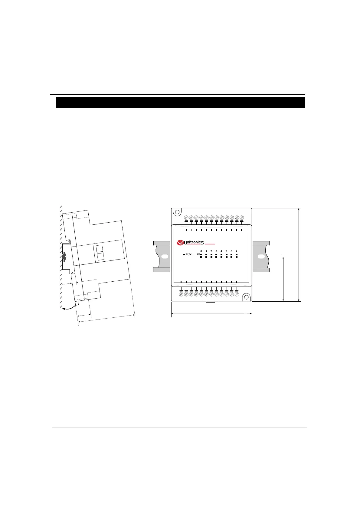
DIN-rail mounting
Snap the device onto the DIN rail as shown below; the module will be squarely situated on the DIN rail.
6
0
m
m
3
.
5
m
m
1
4
m
m
80mm
93mm
44.5mm
IO -DI1 6
98 101112 1314 15
I7I6I5I4I3I2I1I0
I8 I9 I1 0 I1 1 I1 2 I1 3 I1 4 I1 5
PN0V
PN0V
Screw-Mounting
The figure on the next page is drawn to scale. It may be used as a guide for screw-mounting the module.
Mounting screw type: either M3 or NC6-32.