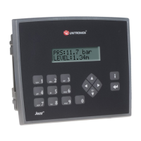
JZ20-UA24/JZ20-J-UA24 Analog Inputs
Note: Shields should be connected at the signal source.
Analog Input wiring, current, 2 or 3 wire, AN2
and AN3
Analog Input wiring, current, 4 wire, AN2 and
AN3
Analog Input wiring, voltage, AN4 and AN5
Note: If either I9 or I10 is wired as an npn digital input, the remaining input may not be wired as an
analog input.
200 to 1820˚C
(300 to 3276˚F)
-200 to 750˚C
(-328 to 1382˚F)
-200 to 760˚C
(-328 to 1400˚F)
-200 to 1250˚C
(-328 to 2282˚F)
-200 to 1300˚C
(-328 to 3214˚F)
0 to 1768˚C
(32 to 3214˚F)
0 to 1768˚C
(32 to 3214˚F
-200 to 400˚C
(-328 to 752˚F)
▪ Thermocouple 0: use T- Input as
negative input and T+ as
positive.
▪ Thermocouple 1: use T- Input as
negative input and T+ as positive.
 Loading...