EasyManua.ls Logo

Unitronics Vision V280 - User Manual

Unitronics Vision V280
15 pages
Print Icon
To Next Page IconTo Next Page
Loading...
Unitronics
1
VisionPLC+HMI
User Guide
Models V230/280/290
This guide provides basic information for Unitronics’ Models V230/280/290 (Non-color Screens).
General Description
Vision PLC+HMIs are programmable logic controllers that comprise an integral operating panel
containing a graphic LCD screen and a keyboard. All models offer the same PLC features.
Operating panel features differ according to model.
V230
LCD + Keyboard
V290
Touchscreen only
Communications
2 serial ports: RS232 (COM1), RS232/RS485 (COM2)
1 CANbus port
The user can order and install an additional port. Available port
types are: RS232/RS485, and Ethernet
Communication Function Blocks include: SMS, GPRS, MODBUS
serial/IP Protocol FB enables PLC to communicate with almost
any external device, via serial or Ethernet communications
I/O Options
Vision supports digital, high-speed, analog, weight and temperature
measurement I/Os via:
Snap-in I/O Modules
Plug into the back of the controller to provide an on-board I/O
configuration
I/O Expansion Modules
Local or remote I/Os may be added via expansion port or CANbus
Information Mode
This mode enables you to:
View & Edit operand values, COM port settings, RTC and screen
contrast/brightness settings
Calibrate the touchscreen
Stop, initialize, and reset the PLC
To enter Information Mode, press the <i> button for several seconds.
Programming
Software,
& Utilities
VisiLogic
Easily configure hardware and write both HMI and Ladder control
applications; the Function Block library simplifies complex tasks
such as PID. Write your application, and then download it to the
controller via the programming cable included in the kit.
Note that in order to program the V290-19-B20B,you must select the
V280/V530 in VisiLogic's Hardware Configuration.
Utilities
These include UniOPC server, Remote Access for remote
programming and diagnostics, and DataXport for run-time data logging
To learn how to use and program the controller, as well as use utilities such
as Remote Access, refer to the VisiLogic Help system.
Question and Answer IconNeed help?

Do you have a question about the Unitronics Vision V280 and is the answer not in the manual?

Unitronics Vision V280 Specifications

General IconGeneral
SeriesVision
Display TypeLCD
Resolution320 x 240 pixels
Input Voltage24 VDC
Power Supply24 VDC
Digital Inputs16
Analog Inputs4
Analog Outputs2
Communication PortsRS-232, RS-485, USB
Programming SoftwareVisiLogic
CPU32-bit
Display Colors65, 536 colors
Memory512 KB
Operating Temperature0°C to 50°C (32°F to 122°F)

Summary

General Description

Communications

Details communication interfaces like RS232, RS485, CANbus, and communication protocols.

I;O Options

Describes how to expand the controller's input/output capabilities using modules.

Information Mode

Explains how to access and use the Information Mode for diagnostics and settings.

Programming Software & Utilities

Covers programming software (VisiLogic) and system utilities like UniOPC, Remote Access.

Operand Types

Kit Contents

Alert Symbols and General Restrictions

Environmental Considerations

UL Compliance

UL Ordinary Location

Specifies UL requirements for mounting in ordinary locations.

UL Hazardous Location Ratings

Details safety precautions and wiring standards for hazardous environments.

Communication and Memory Storage

Clarifies the intended use of USB and SD card ports for communication and storage.

Battery Replacement Safety

Advises on safe battery replacement procedures and data backup.

Mounting Dimensions

V230 and V280 Mounting Dimensions

Provides physical dimensions for V230 and V280 models.

Mounting

V230 Panel Cut-out Dimensions

Shows the precise dimensions required for the panel cut-out for the V230 model.

V280 Panel Cut-out Dimensions

V290 Panel Cut-out Dimensions

Wiring: General

Wiring Guidelines

Earthing the Controller

Power Supply

Communication Ports

Serial Communications

Pinouts

RS232 to RS485 Jumper Settings

Snap-in I;O Module Handling

Removing Snap-in I;O Module

Details the procedure for safely removing a Snap-in I/O module from the controller.

Re-installing Snap-in I;O Module

Details the procedure for correctly reinstalling a Snap-in I/O module.

CANbus

CANbus Wiring

CANbus Connector

Technical Specifications

Technical Specifications: Power Supply

Lists detailed specifications for the power supply, including voltage, current, and consumption.

Technical Specifications: Battery

Provides information on battery backup duration and replacement procedures.

Technical Specifications: Graphic Display

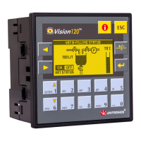
Details the specifications of the graphic display screen, including type and resolution.

Technical Specifications: Keyboard

Lists the specifications related to the controller's keyboard, including key count and type.

Program Memory and Operand Types

Serial and CANbus Communication Specs

I;O Expansion and Configuration

Physical Dimensions and Weight

Panel Mounting Guidelines

Environmental Operating Conditions

Related product manuals