Do you have a question about the Unitronics Vision V130-33-T2 and is the answer not in the manual?
Describes the integrated digital and analog inputs and transistor outputs.
Details the available screen sizes and types for the controllers.
Indicates the presence or absence of a keypad on the controllers.
Lists the standard RS232/RS485 and USB ports integrated into the controllers.
Outlines the availability of user-installable ports like CANbus, Ethernet, and Profibus.
Confirms the controller unit is part of the standard kit.
Notes the inclusion of terminal blocks for wiring connections.
Specifies that a battery is pre-installed in the kit.
Indicates the inclusion of slides for mounting or installation.
Confirms the availability of mounting brackets in the kit.
Notes the inclusion of a rubber seal for environmental protection.
Explains the meaning of Danger, Warning, and Caution symbols used in the document.
Outlines essential guidelines for safe and proper product operation.
Provides critical guidelines for installation environments to prevent damage.
Presents the physical dimensions for V130, V350, V130J, and V350J models.
Details requirements for panel mounting to comply with UL 508 standard.
Specifies the required panel cut-out dimensions for different controller models.
Outlines the step-by-step process for panel mounting the controller.
Emphasizes crucial safety measures and warnings for electrical wiring.
Details the correct method for connecting wires using crimp terminals.
Describes how the 12 inputs can be configured as digital, analog, or high-speed counters.
Details jumper settings for configuring digital inputs 0-11.
Explains jumper settings for inputs 10 and 11 to be digital or analog.
Details jumper settings for analog inputs AN0 and AN1.
Provides wiring diagram for npn (sink) input configuration.
Illustrates wiring for High-Speed Counter (HSC) inputs.
Provides wiring diagram for pnp (source) input configuration.
Details wiring connections for shaft-encoder inputs.
Shows wiring for analog inputs in current and voltage configurations.
Notes that outputs 0 to 6 can be used as PWM outputs.
Details requirements for the external 24VDC power supply, including insulation and rating.
Provides safety warnings regarding power, adapters, and signal isolation.
Explains the use of RS232 for programming and RS485 for multi-drop networks.
Details the pin assignments for RS232 and RS485 communication ports.
Highlights the non-isolated nature of the USB port and grounding requirements.
Provides steps for safely opening the controller, including ESD precautions.
Explains how to access and change I/O jumper settings.
Details how to access and modify communication jumpers for specific models.
Outlines the procedure for correctly reassembling the controller after maintenance.
This document describes the Vision™ PLC+HMI series of micro-PLCs, which are rugged programmable logic controllers featuring built-in operating panels and on-board I/Os. The series includes models V130-33-T2/V130-J-T2, V350-35-T2/V350-J-T2, and V430-J-T2.
The Vision™ PLC+HMI controllers are designed for automation tasks, integrating both PLC and Human Machine Interface (HMI) functionalities into a single compact unit. They come equipped with 12 digital inputs, including 2 analog inputs, 3 high-speed counter (HSC)/shaft-encoder inputs, and 12 transistor outputs. This combination allows for versatile control and monitoring capabilities in various applications.
The input functionality is highly adaptable. All 12 inputs can be used as digital inputs, configurable as either NPN (sink) or PNP (source) via a single jumper setting. Specifically, inputs 10 and 11 can be configured as either digital or analog inputs. Inputs 0, 2, and 4 can function as high-speed counters, part of a shaft-encoder, or as normal digital inputs. Correspondingly, inputs 1, 3, and 5 can serve as counter resets, part of a shaft-encoder, or normal digital inputs. If inputs 0, 2, and 4 are set as high-speed counters without reset, then inputs 1, 3, and 5 can function as normal digital inputs. The 12 transistor outputs provide control signals for external devices, with outputs 0 to 6 also capable of being used as Pulse Width Modulation (PWM) outputs for applications requiring variable control.
Communication capabilities are a key feature of these controllers. The V130/V130J models include a built-in RS232/RS485 serial port (Port 1). The V430J/V350/V350J models offer built-in ports including one USB and one RS232/RS485 (Port 1). It's important to note that for the V430J/V350/V350J models, physically connecting a PC via USB temporarily suspends RS232/RS485 communications on Port 1, which resume once the PC is disconnected. The RS232/RS485 port can be used for downloading programs from a PC, communicating with serial devices, and connecting to SCADA systems. The RS485 functionality also supports multi-drop networks with up to 32 devices. Additionally, users can install optional communication ports, including a CANbus port (V100-17-CAN), an RS232/RS485 port (V100-17-RS4/V100-17-RS4X), an Ethernet port (V100-17-ET2), or a Profibus Slave port (V100-17-PB1). For the V430J/V350/V350J models, which include both RS232/485 and USB ports, only one channel can be used at a time.
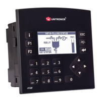
The HMI aspect is provided through integrated screens. The V130-T2/V130J-T2 models feature a 2.4-inch screen with a keypad and function keys. The V350-T2/V350J-T2 models come with a 3.5-inch color touch screen and function keys, but no physical keypad. The V430J-T2 model offers a 4.3-inch color touch screen and function keys, also without a physical keypad. These screens allow for direct interaction with the control system, displaying information and enabling user input.
The controllers are designed for ease of installation and operation. Panel mounting is a common method, requiring a specific cut-out size in the panel. For V130/V350/V130J/V350J models, the cut-out is 92x92 mm (3.622"x3.622"), while for the V430J model, it is 122.5x91.5 mm (4.82"x3.6"). A rubber seal ensures proper fitting and protection. Mounting brackets secure the controller firmly in place. For UL listed models, the device must be panel-mounted on the flat surface of a Type 1 enclosure to meet the UL508 standard. DIN-rail mounting is also supported for V130/V350/V130J/V350J models, allowing for quick and secure installation in industrial cabinets.
Wiring procedures emphasize safety and reliability. Users are instructed to use crimp terminals and specific wire gauges (3.31 mm² - 0.13 mm² wire, 12-16 AWG). Wires should be stripped to a precise length and inserted completely into the terminals before tightening. It is crucial to avoid running input or output cables through the same multi-core cable or sharing the same wire to prevent noise interference. The controller and I/O signals must be connected to the same 0V signal. Shields for analog inputs should be connected at the signal's source, and the 0V signal of the analog input must be connected to the controller's 0V.
Power supply requirements specify an external 24VDC power supply with double insulation, rated as SELV/PELV/Class2/Limited Power. An external circuit breaker is necessary to guard against short-circuiting. Separate wires should be used for the functional earth line and the 0V line to the system earth ground. To maximize system performance and avoid electromagnetic interference, it is recommended to mount the controller on a metal panel and connect all common and ground connections directly to the system's earth ground using the shortest and thickest possible wire.
Communication parameters for RS232/RS485 can be configured via jumpers (for V130/V350/V130J/V350J models) or DIP switches (for V430J). These settings determine whether the port operates as RS232 or RS485, and if RS485 termination is enabled. The USB port, available on V430J/V350/V350J models, is used for programming, OS downloads, and PC access. It is important to ensure that the PC and the controller are grounded to the same potential when using the USB port, as it is not isolated.
The design allows for user-level maintenance and configuration adjustments. Accessing the I/O jumpers and communication jumpers requires opening the controller. This involves turning off the power supply, disconnecting the unit, and removing the back cover by unscrewing four corner screws. When handling the internal PCB board, users are advised to discharge any electrostatic charge by touching a grounded object and to hold the PCB by its connectors, avoiding direct contact with the board itself.
Once the controller is open, I/O settings can be changed by adjusting the relevant jumpers according to the provided tables. For communication settings on V130/V350/V130J/V350J models, the I/O PCB board needs to be gently pulled off to access the communication jumpers. After making the necessary adjustments, the board should be carefully replaced, ensuring pins fit correctly into their receptacles without forcing. The back cover must then be securely fastened before powering up the controller.
The manual provides clear warnings and cautions to ensure safe operation and prevent damage. These include instructions not to touch live wires, to use appropriate circuit protection devices, and not to connect unused pins. Double-checking all wiring before powering on the device is emphasized. Environmental considerations are also outlined, advising against installation in areas with excessive dust, corrosive gases, moisture, or extreme temperatures, and requiring adequate ventilation space around the controller. These guidelines contribute to the long-term reliability and maintainability of the device.
| Manufacturer | Unitronics |
|---|---|
| Series | Vision |
| Model | V130-33-T2 |
| Display Type | LCD |
| Touchscreen | Yes |
| Number of Analog Inputs | 2 |
| Number of Digital Outputs | 12 |
| Output Type | Relay |
| Communication Ports | RS-232, RS-485, USB |
| Programming Software | VisiLogic |
| Real-Time Clock | Yes |
| Input Voltage | 24 VDC |
| Operating Voltage | 24 VDC |
| Input Type | Digital and Analog |
| Analog Outputs | 0 |
| Protection Rating | IP65 |
| CPU | 32-bit RISC |