Do you have a question about the Unitronics Vision V120 and is the answer not in the manual?
Overview of micro-PLC+HMIs and where to find detailed documentation.
Explanation of symbols and general safety guidelines for product use.
Guidelines for installing the device in various environmental conditions.
Instructions for mounting the controller onto a panel, including cut-out size.
Steps for securely snapping the controller onto a DIN rail.
Safety precautions and general guidelines for wiring the controller.
Steps and guidelines for connecting wires using crimp terminals.
Recommendations for earthing the product to maximize performance and avoid EMI.
Information on UL listing for hazardous and ordinary locations.
Requirements for mounting the device in UL ordinary locations.
Information on UL certification for hazardous locations, Class I, Division 2.
Ratings for relay outputs in hazardous and non-hazardous environments.
Operating temperature limits for controllers in different environments.
Procedure and precautions for replacing the controller battery.
Detailed specifications for V120-22-R2C, including power, inputs, and counters.
Important safety warnings regarding wiring and product usage.
Details on analog input types, conversion, and connections.
Information on digital output types, isolation, and current.
Details on relay output type, isolation, current, and contact protection.
Information about the RTC, battery backup, and operating conditions.
Detailed specifications for M91-2-R2C, including power, inputs, and counters.
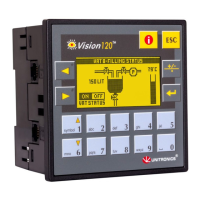
Details on the graphic display and keypad features.
Information on PLC program memory, timers, and counters.
Details on RS232/RS485, I/O expansion, and CANbus ports.
Settings for JP1 to configure digital input type (npn/pnp).
Settings for JP2 to configure digital input voltage (12V/24VDC).
Settings for JP3/JP4 for analog input type (Voltage/Current).
Settings for JP5/JP6 for power supply voltage range.
Note on different controller models' serial and CANbus options.
Configuration of RS232 or RS485 serial ports for programming and networking.
Pin assignments for RS232 and RS485 serial ports.
Instructions for changing jumpers to adapt serial ports for RS485.
Step-by-step guide on how to safely open the controller to access jumpers.
Tables detailing jumper settings for M91 series for RS232/RS485 configuration.
Tables detailing jumper settings for V120 series for RS232/RS485 configuration.
Information on creating a decentralized control network using CANbus.
Guidelines for wiring the CANbus network, including cable and terminators.
Diagram and description of the CANbus connector pinout.
| Brand | Unitronics |
|---|---|
| Model | Vision V120 |
| Category | Controller |
| Language | English |