Note that different controller models offer different serial and CANbus communication options. To see
which options are relevant, check your controller’s technical specifications.
▪ Turn off power before making communications connections.
▪ Note that the serial ports are not isolated.
▪ Signals are related to the controller’s 0V; the same 0V is used by the power supply.
▪ Always use the appropriate port adapters.
This series comprises 2 serial port can be set to either RS232 or RS485 according to jumper
settings. By default, the ports are set to RS232.
Use RS232 to download programs from a PC, and to communicate with serial devices and
applications, such as SCADA.
Use RS485 to create a multi-drop network containing up to 32 devices.
Caution ■ The serial ports are not isolated. If the controller is used with a non-
isolated external device, avoid potential voltage that exceeds ± 10V.
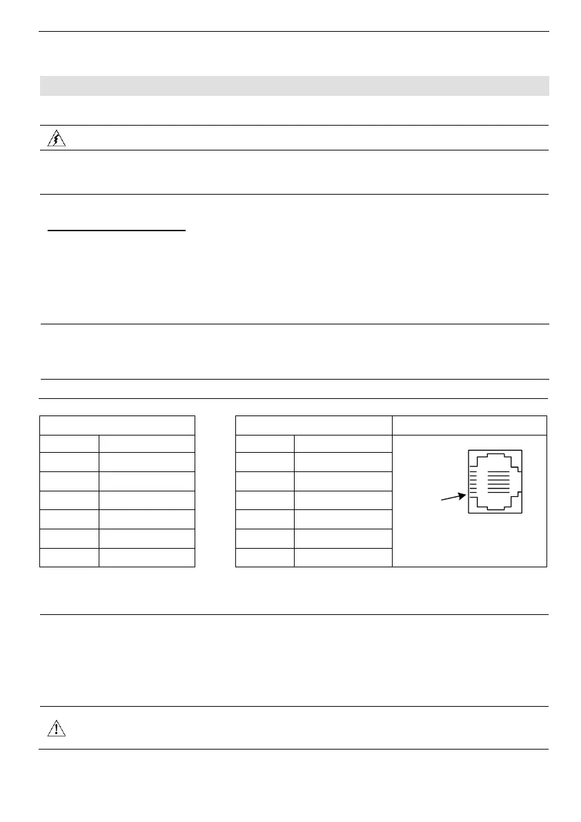
The pinouts below show the signals between the adapter and port.
*Standard programming cables do not provide connection points for pins 1 and 6.
RS232 to RS485: Changing Jumper Settings
▪ To access the jumpers, open the controller and then remove the module’s PCB board. Before
you begin, turn off the power supply, disconnect and dismount the controller.
▪ When a port is adapted to RS485, Pin 1 (DTR) is used for signal A, and Pin 6 (DSR) signal is
used for signal B.
▪ If a port is set to RS485, and flow signals DTR and DSR are not used, the port can also be used
to communicate via RS232; with the appropriate cables and wiring.
▪ Before performing these actions, touch a grounded object to discharge any electrostatic
charge.
▪ Avoid touching the PCB board directly. Hold the PCB board by its connectors.