Do you have a question about the Unitronics Vision OPLC V350-35-TR20 and is the answer not in the manual?
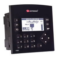
Rugged programmable logic controllers with on-board I/O and touchscreen interface.
Features RS232/RS485, optional modules, and supports various I/O types and expansion.
Press 'i' button to view/edit parameters and control PLC states.
Includes VisiLogic for development and utilities for remote access and data logging.
Utilize Micro SD for datalogs/backups and Data Tables for recipes/logs.
Lists the Vision controller, I/O connectors, battery, and programming cable.
Explains symbols indicating potential physical and property damage risks.
Advises on avoiding dust, moisture, heat, vibration, and ensuring proper ventilation.
Detailed steps for cutting a panel and securely installing the controller.
Instructions for snapping the controller onto a standard DIN rail.
Includes warnings about live wires, circuit protection, torque, and wire types.
Step-by-step guide for stripping wire, inserting into terminals, and securing connections.
Details on 12 inputs, configurable as digital, analog, or high-speed counters via jumpers.
Tables and diagrams for setting digital, analog, and counter input types using jumpers.
Diagrams for npn and pnp wiring for digital and high-speed counter inputs.
Connection diagram for shaft-encoder inputs (HSC0, HSC1, HSC2).
Wiring for current/voltage analog inputs using 2/3-wire or 4-wire transmitters.
Diagram showing connections for 6 relay outputs (110/220VAC and 24VDC).
Methods to protect relay contacts using clamping diodes or RC snubbers.
Requires 24VDC supply with double insulation; includes wiring precautions.
Recommendations for connecting ground for optimal system performance and EMI reduction.
Details on Port 1 (RJ-11) for RS232/RS485, including default settings and usage.
Pinout details for RS232 and RS485 communication ports.
Explains jumper settings for changing communication standards and termination.
Safety precautions and steps for removing the controller's back cover.
Guide to changing I/O settings after exposing the I/O board.
Instructions for accessing and changing communication jumpers.
Steps for correctly replacing the I/O board and back cover.
| Resolution | 320 x 240 pixels |
|---|---|
| Input Voltage | 24 VDC |
| Communication Ports | RS-232, RS-485, USB, Ethernet |
| Programming Software | UniLogic |
| Touch Panel | Yes |
| Power Supply | 24 VDC |
| Display Type | TFT |
| Display Size | 3.5 inches |
| CPU | 32-bit |
| Analog Outputs | 2 |
| Protection Class | IP65 |