Do you have a question about the Unitronics Vision V570-57-T40B and is the answer not in the manual?
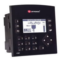
V570 OPLCs feature a built-in 5.7" color touchscreen with a virtual keyboard for data entry.
Supports isolated RS232/RS485, CANbus, and optional Ethernet ports with various communication protocols.
Supports digital, high-speed, analog I/Os via Snap-in and Expansion Modules for flexible configurations.
Enables touchscreen calibration, operand/settings viewing, and PLC control (stop, initialize, reset).
Includes VisiLogic for development and utilities like UniOPC Server, Remote Access, and DataXport.
Utilizes SD card for logs, alarms, trends, data tables; supports export to Excel and cloning.
Lists included items: Vision controller, power/CANbus connectors, cable, brackets, seal, and CD.
Explains symbols indicating danger, warning, and caution for safe operation and handling.
Provides guidelines on avoiding hazardous environments and ensuring proper ventilation for the controller.
Step-by-step guide for inserting the battery, including cover removal and polarity alignment.
Presents the physical dimensions of the controller and its I/O module for planning.
Detailed steps for creating a panel cut-out, inserting the controller, and securing it with brackets.
Safety instructions for wiring, including avoiding live wires, short-circuits, and using correct torque.
Instructions for using crimp terminals, stripping wire, and ensuring proper connection in terminals.
Specifies voltage requirements (12/24VDC) and permissible input ranges for different controller models.
Guidance on earthing the controller and power supply for optimal performance and interference reduction.
Details RS232 and RS485 pinouts and how to change COM port settings using DIP switches.
Explains CANbus port usage, wiring with twisted-pair cable, and network terminator requirements.
| Brand | Unitronics |
|---|---|
| Model | Vision V570-57-T40B |
| Category | Controller |
| Language | English |