Do you have a question about the Unitronics Vision120 and is the answer not in the manual?
Details controller communication ports like RS232/RS485 and CANbus.
Details onboard and expansion I/O configurations for controllers.
Describes the use of VisiLogic freeware for HMI and Ladder control.
Lists the items included in the standard controller kit.
Explains the meaning of Danger, Warning, and Caution symbols.
Precautions regarding installation environment and ventilation.
Provides physical dimensions of the Vision120 controller.
Step-by-step guide for mounting the controller in a panel.
Instructions for mounting the controller on a DIN rail.
Information on controller I/O configurations and expansion modules.
Warnings about live wires and connecting unused pins.
Details controller power supply requirements and conditions.
Details on setting ports to RS232 or RS485 via jumper.
Procedure for grounding the power supply to avoid interference.
Pin configurations for RS232 and RS485 ports.
Steps to open the controller and access the PCB board.
Safety measures for handling electronic components.
Table for RS232 and RS485 jumper configurations for COM1 and COM2.
Table for RS485 termination jumper settings.
Instructions for connecting CANbus devices using twisted-pair cable.
Details the pin assignments for the CANbus connector.
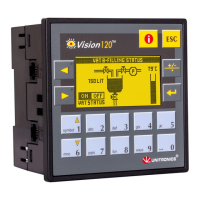
The Unitronics Vision120™ OPLC (micro-OPLC) is a rugged programmable logic controller that integrates an on-board I/O configuration and a built-in operating panel with a graphic LCD screen and a keypad. It is designed for both HMI and Ladder control applications, which can be programmed using the VisiLogic freeware.
The Vision120 OPLC serves as a compact and robust control solution, combining the functionalities of a programmable logic controller and a human-machine interface. It allows for the execution of control logic and the display of operational data through its integrated graphic LCD and keypad. The device supports various communication protocols and I/O options, making it versatile for different automation tasks.
| Brand | Unitronics |
|---|---|
| Model | Vision120 |
| Category | Controller |
| Language | English |