Installation Guide 10/06
Unitronics 5
You must use an external circuit protection device.
Install an external circuit breaker. Guard against short-
circuiting in external wiring.
Double-check all wiring before turning on the power
supply.
Do not connect either the ‘Neutral or ‘Line’ signal of the
110/220VAC to device’s 0V pin.
In the event of voltage fluctuations or non-conformity to
voltage power supply specifications, connect the device
to a regulated power supply.
Earthing the Power Supply
To maximize system performance, avoid electromagnetic interference by:
Mounting the controller on a metal panel.
Earthing the controller’s power supply: connect one end of a 14 AWG wire to the chassis
signal; connect the other end to the panel.
Note: The wire used to earth the power supply must not exceed 10 cm in length. If your
conditions do not permit this, do not earth the power supply
Communication Ports
This series comprises 2 serial ports that may be set to either RS232 or RS485. Certain models also
comprise CANbus ports. Check your controller’s technical specifications.
Turn off power before making communications connections.
Caution
Signals are related to the controller’s 0V; the same 0V is used by the power supply.
Always use the appropriate port adapters.
Serial Communications
The serial ports are type RJ-11 and may be set to either RS232 or RS485 via jumper as described
on page 6. By default, the ports are set to RS232.
Use RS232 to download programs from a PC, and to communicate with serial devices and
applications, such as SCADA.
Use RS485 to create a multi-drop network containing up to 32 devices.
Caution
The serial ports are not isolated. If the controller is used with a non-isolated external
device, avoid potential voltage that exceeds ± 10V.
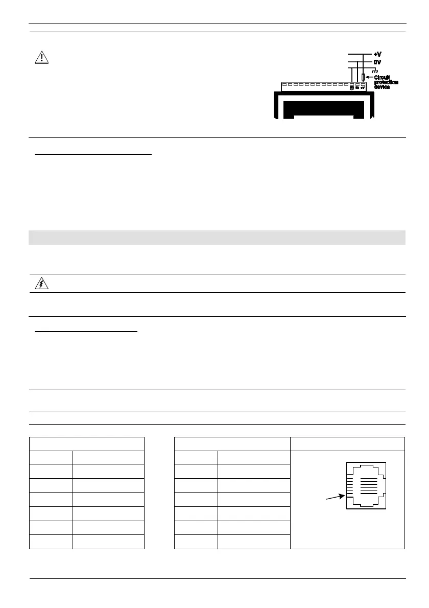
Pinouts
The pinouts below show the signals between the adapter and port.
RS232 RS485 Controller Port
Pin # Description Pin # Description
1* DTR signal
1 A signal (+)
2 0V reference
2 (RS232 signal)
3 TXD signal
3 (RS232 signal)
4 RXD signal
4 (RS232 signal)
5 0V reference
5 (RS232 signal)
6* DSR signal*
6 B signal (-)
Pin #1
*Standard programming cables do not provide connection points for pins 1 and 6.