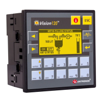
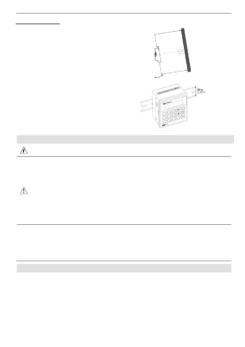
1. Snap the controller onto the DIN rail as
shown in the figure to the right.
2. When properly mounted, the controller is
squarely situated on the DIN-rail as
shown in the figure to the right.
▪ Do not touch live wires.
▪ This equipment is designed to operate only in SELV/PELV/Class 2/Limited Power
environments.
▪ All power supplies in the system must include double insulation. Power supply outputs
must be rated as SELV/PELV/Class 2/Limited Power.
▪ Do not connect either the ‘Neutral or ‘Line’ signal of the 110/220VAC to device’s 0V pin.
▪ All wiring activities should be performed while power is OFF.
▪ Use over-current protection, such as a fuse or circuit breaker, to avoid excessive currents
into the power supply connection point.
▪ Unused points should not be connected (unless otherwise specified). Ignoring this
directive may damage the device.
▪ Double-check all wiring before turning on the power supply.
▪ To avoid damaging the wire, do not exceed a maximum torque of:
- Controllers offering a terminal block with pitch of 5mm: 0.5 N·m (5 kgf·cm).
- Controllers offering a terminal block with pitch of 3.81mm f 0.2 N·m (2 kgf·cm).
▪ Do not use tin, solder, or any substance on stripped wire that might cause the wire
strand to break.
▪ Install at maximum distance from high-voltage cables and power equipment.
Use crimp terminals for wiring;
- Controllers offering a terminal block with pitch of 5mm: 26-12 AWG wire (0.13 mm
2
–3.31 mm
2
).
- Controllers offering a terminal block with pitch of 3.81mm: 26-16 AWG wire (0.13 mm
2
– 1.31 mm
2
).