1. Strip the wire to a length of 7±0.5mm (0.250–0.300”).
2. Unscrew the terminal to its widest position before inserting a wire.
3. Insert the wire completely into the terminal to ensure a proper connection.
4. Tighten enough to keep the wire from pulling free.
▪ Use separate wiring ducts for each of the following groups:
▪ Group 1: Low voltage I/O and supply lines, communication lines.
▪ Group 2: High voltage Lines, Low voltage noisy lines like motor driver outputs.
Separate these groups by at least 10cm (4"). If this is not possible, cross the ducts at a 90˚angle.
▪ For proper system operation, all 0V points in the system should be connected to the
system 0V supply rail.
To maximize system performance, avoid electromagnetic interference as follows:
▪ Use a metal cabinet.
▪ Connect the 0V terminal to the earth ground of the system at one point, preferably as near to the
controller as possible.
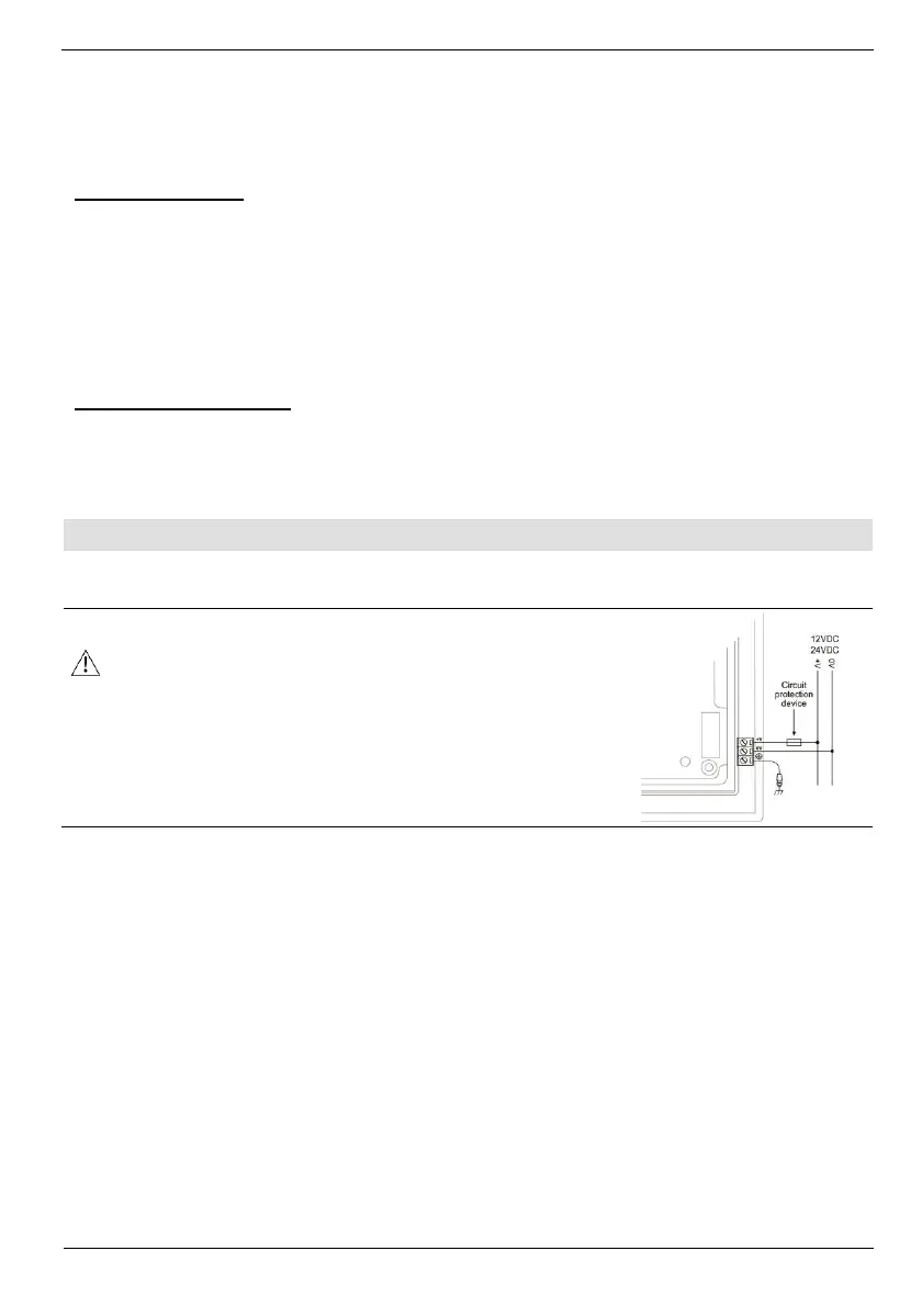
The controller requires an external 12 or 24VDC power supply. The permissible input voltage
range is 10.2-28.8VDC, with less than 10% ripple.
▪ You must use an external circuit protection device
▪ Install an external circuit breaker. Guard against short-
circuiting in external wiring
▪ Double-check all wiring before turning on the power
supply
In the event of voltage fluctuations or non-conformity to
voltage power supply specifications, connect the device to a
regulated power supply