▪ Turn off power before making communications connections
▪ Signals are related to the controller’s 0V; this is the same 0V used by the power supply
▪ Always use the appropriate port adapters
▪ The serial ports are not isolated. If the controller is used with a non-isolated external
device, avoid potential voltage that exceeds ± 10V
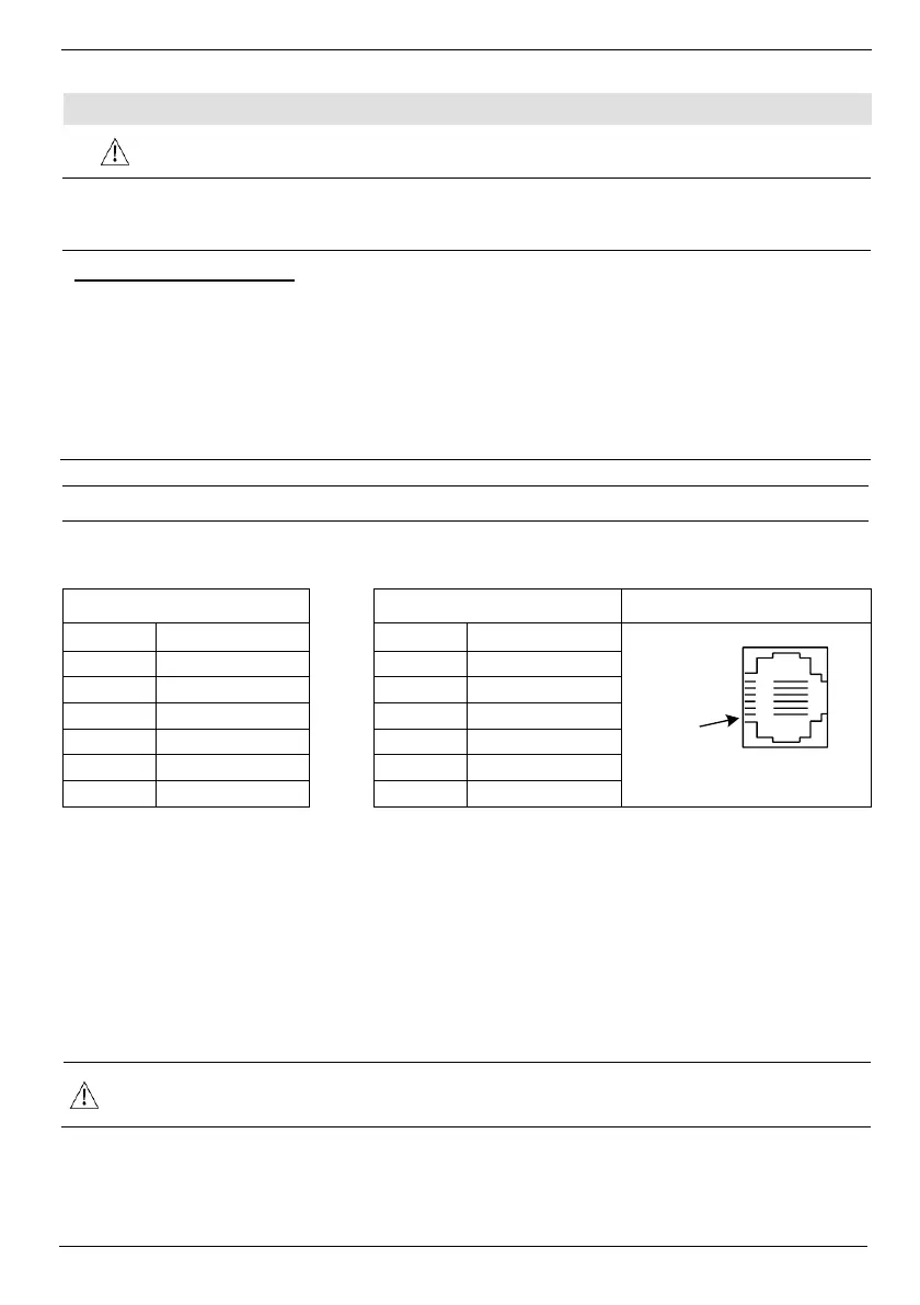
This series comprises 2 RJ-11-type serial ports and a CANbus port.
COM1 is RS232 only. COM2 may be set to either RS232 or RS485 via jumper as described below.
By default, the port is set to RS232.
Use RS232 to download programs from a PC, and to communicate with serial devices and
applications, such as SCADA.
Use RS485 to create a multi-drop network containing up to 32 devices.
▪ COM1 & 2 are not isolated
To connect a PC to a port that is set to RS485, remove the RS485 connector, and connect the PC
to the PLC via the programming cable. Note that this is possible only if flow control signals are not
used (which is the standard case).
*Standard programming cables do not provide connection points for pins 1 and 6.
** When a port is adapted to RS485, Pin 1 (DTR) is used for signal A, and Pin 6 (DSR) signal
is used for signal B.
RS232 to RS485: Changing Jumper Settings
The port is set to RS232 by factory default.
To change the settings, first remove the Snap-in I/O Module, if one is installed, and then set the
jumpers according to the following table.
Note:
For V230/V280/V290 modules only there is a small window as described on page 6 for
jumper setting so there is no need to open the controller.
▪ Before you begin, touch a grounded object to discharge any electrostatic charge
1. Before removing a Snap-in I/O Module or opening the controller, you must turn off the power