UMI-B1 UL Series Inverter Keypad operation procedure
22
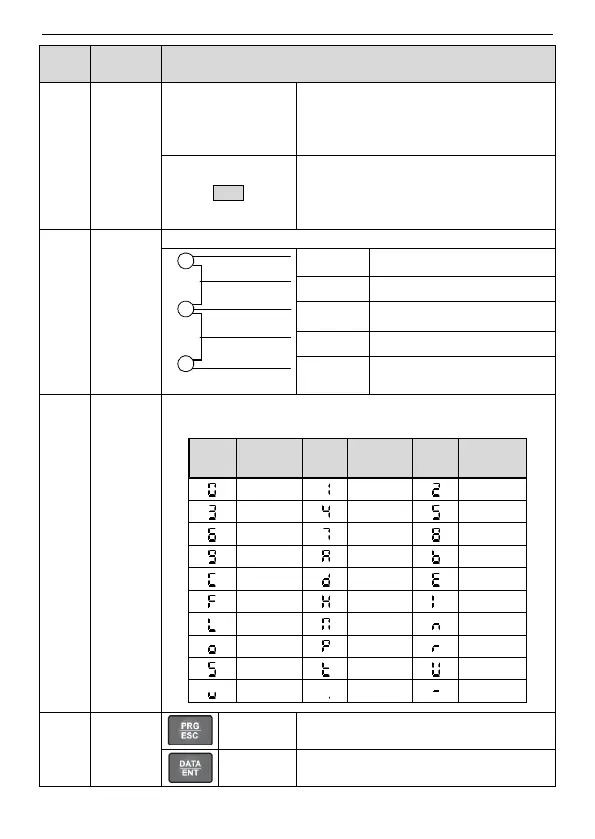
means the inverter is in the terminals
operation state; LED on means the inverter
is in the remote communication control
state.
LED for faults
LED on when the inverter is in the fault
state; LED off in normal state; LED blinking
means the inverter is in the pre-alarm state.
Mean the unit displayed currently
5-figure LED display displays various monitoring data and alarm
code such as set frequency and output frequency.
0
3
6
9
C
F
L
O
S
v
1
4
7
A
d
H
N
P
t
.
2
5
8
b
E
l
n
r
U
-
Displayed
character
Displayed
character
Displayed
character
Corresponding
character
Corresponding
character
Corresponding
character
Enter or escape from the first level menu
and remove the parameter quickly
Enter the menu step-by-step
Confirm parameters
 Loading...