UMI-B1 UL Series Inverter Fault tracking
103
6.2 Fault solution
• Only qualified electricians are allowed to maintain the inverter. Read
the safety instructions in chapter Safety precautions before working on
the inverter.
6.2.1 Alarm and fault indications
Fault is indicated by LEDs. See Operation Procedure. When TRIP light is on, an alarm
or fault message on the panel display indicates abnormal inverter state. Using the
information given in this chapter, most alarm and fault cause can be identified and
corrected. If no, contact the UNITRONICS office.
6.2.2 How to reset
The inverter can be reset by pressing the keypad key STOP/RST, through digital input,
or by switching the power light. When the fault has been removed, the motor can be
restarted.
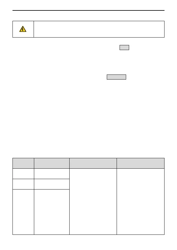
6.2.3 Fault instruction and solution
Do as the following after the inverter fault:
1. Check to ensure there is nothing wrong with the keypad. If no, contact the local
UNITRONICS office.
2. If there is nothing wrong, check P07 and ensure the corresponding recorded fault
parameters to confirm the real state when the current fault occurs by all parameters.
3. See the following table for detailed solution and check the corresponding abnormal
state.
4. Eliminate the fault and ask for relative help.
5. Check to eliminate the fault and carry out fault reset to run the inverter.
Over-current when
acceleration
1. The acceleration or
deceleration is too fast.
2. The voltage of the grid
is too low.
3. The power of the
inverter is too low.
4. The load transients or
is abnormal.
5. The grounding is short
circuited or the output is
phase loss.
6. There is strong
external interference.
1. Increase the ACC time
2. Check the input power
3. Select the inverter with
a larger power
4. Check if the load is
short circuited (the
grounding short circuited
or the wire short circuited)
or the rotation is not
smooth.
5. Check the output
configuration.
6. Check if there is strong
Over-current when
deceleration
Over-current when
constant speed
running
 Loading...