EasyManua.ls Logo

Unitronics US5-B5-RA28 - Page 13

Unitronics US5-B5-RA28
18 pages
Print Icon
To Next Page IconTo Next Page
To Previous Page IconTo Previous Page
Loading...
UniStream
®
Built-in
Unitronics
13
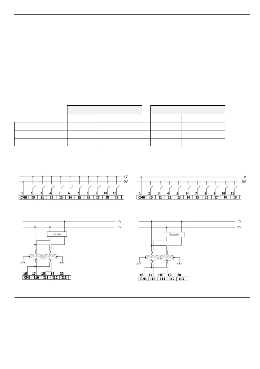
Wiring the Digital Inputs
The digital inputs are arranged in two isolated groups:
I0-I9 share common CM0
I10-I13 share common CM1
Each group may be wired together as sink or source.
Inputs I10, I11, I12 and I13 can be configured as either normal digital inputs or as high
speed inputs that can receive high speed pulse signals from sensors or shaft encoders.
High Speed Input Modes
Following are the different pin assignments for the high speed channels:
Channel 1
Channel 2
I10
I11
I12
I13
Quadrature
Phase A
Phase B
Phase A
Phase B
Pulse+Direction
Pulse
Direction
Pulse
Direction
Pulse
Pulse
Normal digital
Pulse
Normal digital
NOTE
Input modes are set both by wiring and software.
Input wiring, sink
Input wiring, source
High Speed Input wiring, sink
High Speed Input wiring, source
NOTE
Use sink input wiring to connect a sourcing (pnp) device.
Use source input wiring to connect a sinking (npn) device.

Related product manuals