EasyManua.ls Logo

Unitronics Vision OPLC VV570-57-T20B-J - User Manual

Unitronics Vision OPLC VV570-57-T20B-J
8 pages
Print Icon
To Next Page IconTo Next Page
Loading...
Unitronics 1
Vision™ OPLC™
Installation Guide
V570-57-T40B, V570-57-T20B,
& V570-57-T20B-J
This guide provides basic information for Unitronics’ controllers V570-57-T40B, V570-57-T20B &
V570-57-T20B-J.
General Description
V570 OPLCs are programmable logic controllers that comprise a built-in operating panel containing a
5.7” Color Touchscreen which displays a virtual keyboard when the application requires the operator
to enter data.
Communications
2 isolated RS232/RS485 ports
Isolated CANbus port
The user can order and install an Ethernet port
Communication Function Blocks include: SMS, GPRS, MODBUS
serial/IP Protocol FB enables PLC to communicate with almost any
external device, via serial or Ethernet communications
I/O Options
V570 supports digital, high-speed,
analog, weight and temperature
measurement I/Os via:
Snap-in I/O Modules
Plug into the back of the
controller to provide an on-
board I/O configuration
I/O Expansion Modules
Local or remote I/Os may be
added via expansion port or
CANbus.
Installation instructions and other data may be found in the module’s technical
specification sheet.
Information Mode
This mode enables you to:
Calibrate the touchscreen
View & Edit operand values, COM port settings, RTC and screen
contrast/brightness settings
Stop, initialize, and reset the PLC
To enter Information Mode, press the <i> button for several seconds.
Programming
Software,
& Utilities
The Unitronics Setup CD contains VisiLogic software and other utilities
VisiLogic
Easily configure hardware and write both HMI and Ladder control
applications; the Function Block library simplifies complex tasks
such as PID. Write your application, and then download it to the
controller via the programming cable included in the kit.
Utilities
These include UniOPC server, Remote Access for remote
programming and diagnostics, and DataXport for run-time data
logging.
To learn how to use and program the controller, as well as use utilities such as
Remote Access, refer to the VisiLogic Help system.
Question and Answer IconNeed help?

Do you have a question about the Unitronics Vision OPLC VV570-57-T20B-J and is the answer not in the manual?

Summary

General Description

Communications

Details communication ports (RS232/RS485, CANbus, Ethernet) and protocols supported.

I;O Options

Covers V570's support for digital, high-speed, analog, weight, and temperature I/Os via modules.

Information Mode

Explains how to use Information Mode for touchscreen calibration and controller status adjustments.

Programming Software & Utilities

Introduces VisiLogic software for programming and lists essential utilities like UniOPC server.

Removable Memory Storage

Data Tables

Standard Kit Contents

Danger Symbols

Environmental Considerations

Inserting the Battery

Mounting Dimensions

Panel Mounting

Wiring

Wiring Procedure

Step-by-step guide for stripping wires and connecting them to terminals correctly.

Power Supply

Specifies V570 power supply requirements, input voltage ranges, and safety precautions.

Earthing the Power Supply

Instructions for earthing the controller's power supply to minimize electromagnetic interference.

Communication Ports

Pinouts

Details the pin configurations for the RS232 and RS485 serial communication ports.

RS232 to RS485: Changing DIP Switch Settings

Guide to changing serial port settings from RS232 to RS485 using DIP switches.

Removing a Snap-in I;O Module

Re-installing a Snap-in I;O Module

CANbus

CANbus Wiring

Guidelines for wiring the CANbus network, including cable types and termination resistors.

CANbus Connector

Details the pinout and function of the CANbus connector for network connections.

Overview

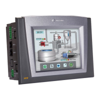
The Unitronics V570-57-T40B, V570-57-T20B, and V570-57-T20B-J are programmable logic controllers (PLCs) that integrate a built-in operating panel with a 5.7-inch color touchscreen. This touchscreen displays a virtual keyboard for operator data entry when required by the application.

Function Description:

These OPLCs are designed for industrial control applications, combining the functionality of a PLC with a human-machine interface (HMI). They support various communication protocols and I/O options, making them versatile for different automation tasks. The controllers can be programmed to manage complex processes, display real-time data, and allow operator interaction through the touchscreen.

Important Technical Specifications:

  • Display: 5.7" Color Touchscreen with virtual keyboard.
  • Communication Ports:
    • Two isolated RS232/RS485 ports. These ports are RJ-11 type and can be configured for either RS232 or RS485 via DIP switches. RS232 is used for program downloads from a PC and communication with serial devices (e.g., SCADA). RS485 supports multi-drop networks with up to 32 devices.
    • One isolated CANbus port. This port can be used to create a decentralized control network using CANopen (up to 127 controllers/external devices), CANLayer 2, or Unitronics' proprietary UniCAN (up to 60 controllers with 512 data bytes per scan).
    • Optional Ethernet port (user-orderable and installable).
  • Communication Function Blocks: Include SMS, GPRS, and MODBUS serial/IP Protocol FBs, enabling communication with almost any external device via serial or Ethernet.
  • I/O Options:
    • Snap-in I/O Modules: Plug into the back of the controller for on-board I/O configuration (digital, high-speed, analog, weight, temperature measurement).
    • I/O Expansion Modules: Local or remote I/Os can be added via an expansion port or CANbus.
  • Power Supply:
    • V570-57-T20B & V570-57-T20B-J: Requires an external 12 or 24VDC power supply. Permissible input voltage range: 10.2-28.8VDC (less than 10% ripple).
    • V570-57-T40B: Requires an external 24VDC power supply. Permissible input voltage range: 20.4-28.8VDC (less than 10% ripple).
    • A non-isolated power supply can be used if a 0V signal is connected to the chassis.
  • Removable Memory Storage: Supports SD cards for storing datalogs, alarms, trends, data tables, exporting to Excel, backing up Ladder, HMI & OS, and 'cloning' PLCs.
  • Data Tables: Enable setting recipe parameters and creating datalogs.

Usage Features:

  • Programming: The Unitronics Setup CD includes VisiLogic software, which allows users to easily configure hardware and write both HMI and Ladder control applications. The Function Block library simplifies complex tasks like PID. Applications are downloaded to the controller via a programming cable.
  • Utilities: The software package includes UniOPC server, Remote Access for remote programming and diagnostics, and DataXport for run-time data logging.
  • Information Mode: Accessible by pressing the <i> button for several seconds, this mode allows users to:
    • Calibrate the touchscreen.
    • View and edit operand values, COM port settings, RTC, and screen contrast/brightness settings.
    • Stop, initialize, and reset the PLC.
  • Battery Insertion: A battery is supplied (not installed) to preserve data in case of power-off. It must be inserted into the battery holder on the rear of the controller, ensuring correct polarity.
  • Mounting: The controller is designed for panel mounting. A panel cut-out must be made according to specified dimensions (146.6 mm x 124.5 mm for the opening, 197 mm x 146.6 mm overall). The controller slides into the cut-out with a rubber seal, and four mounting brackets secure it to the panel. The mounting panel cannot be more than 5 mm thick.
  • Wiring:
    • Crimp terminals are recommended for wiring, using 26-12 AWG wire (0.13 mm²–3.31 mm²).
    • Wires should be stripped to 7±0.5mm (0.250–0.300 inches) and inserted completely into the terminal, then tightened.
    • External circuit breakers and appropriate circuit protection devices must be installed.
    • Double-check all wiring before powering on.
    • Avoid connecting unused pins.
    • Do not exceed a maximum torque of 0.5 N·m (5 kgf·cm) when tightening wires.
    • Do not use tin, solder, or any substance on stripped wire.
    • Install at maximum distance from high-voltage cables and power equipment.
  • Earthing: To maximize system performance and avoid electromagnetic interference, the controller should be mounted on a metal panel, and its power supply should be earthed. A 14 AWG wire, ideally not exceeding 10 cm, should connect the chassis signal to the panel.
  • CANbus Wiring: Use twisted-pair cable (DeviceNet® thick shielded twisted pair cable is recommended). Network terminators (121Ω, 1/4W) must be placed at each end of the CANbus network. The ground signal should be connected to earth at only one point, near the power supply.

Maintenance Features:

  • Snap-in I/O Module Removal/Re-installation: Modules can be removed by pressing four buttons on the sides of the controller and gently rocking the module. Re-installation involves aligning circular guidelines and applying even pressure until a 'click' is heard.
  • Environmental Considerations:
    • Avoid installation in areas with excessive or conductive dust, corrosive or flammable gas, moisture, rain, excessive heat, regular impact shocks, or excessive vibration.
    • Ensure 10mm ventilation space between the controller's top/bottom edges and enclosure walls.
    • Do not expose the unit to water or allow debris to fall inside during installation.
  • Safety Guidelines:
    • Always turn off power before making communication connections or wiring.
    • Do not touch live wires.
    • Do not connect/disconnect the device when power is on to avoid damage.
    • Do not use parameters that exceed permissible levels.
    • Only qualified service personnel should open the device or carry out repairs.
    • Dispose of the product according to local and national standards.
  • LCD Screen: Note that the LCD screen may have a single pixel that is permanently either black or white.

Unitronics Vision OPLC VV570-57-T20B-J Specifications

General IconGeneral
BrandUnitronics
ModelVision OPLC VV570-57-T20B-J
CategoryNetwork Router
LanguageEnglish

Related product manuals