38
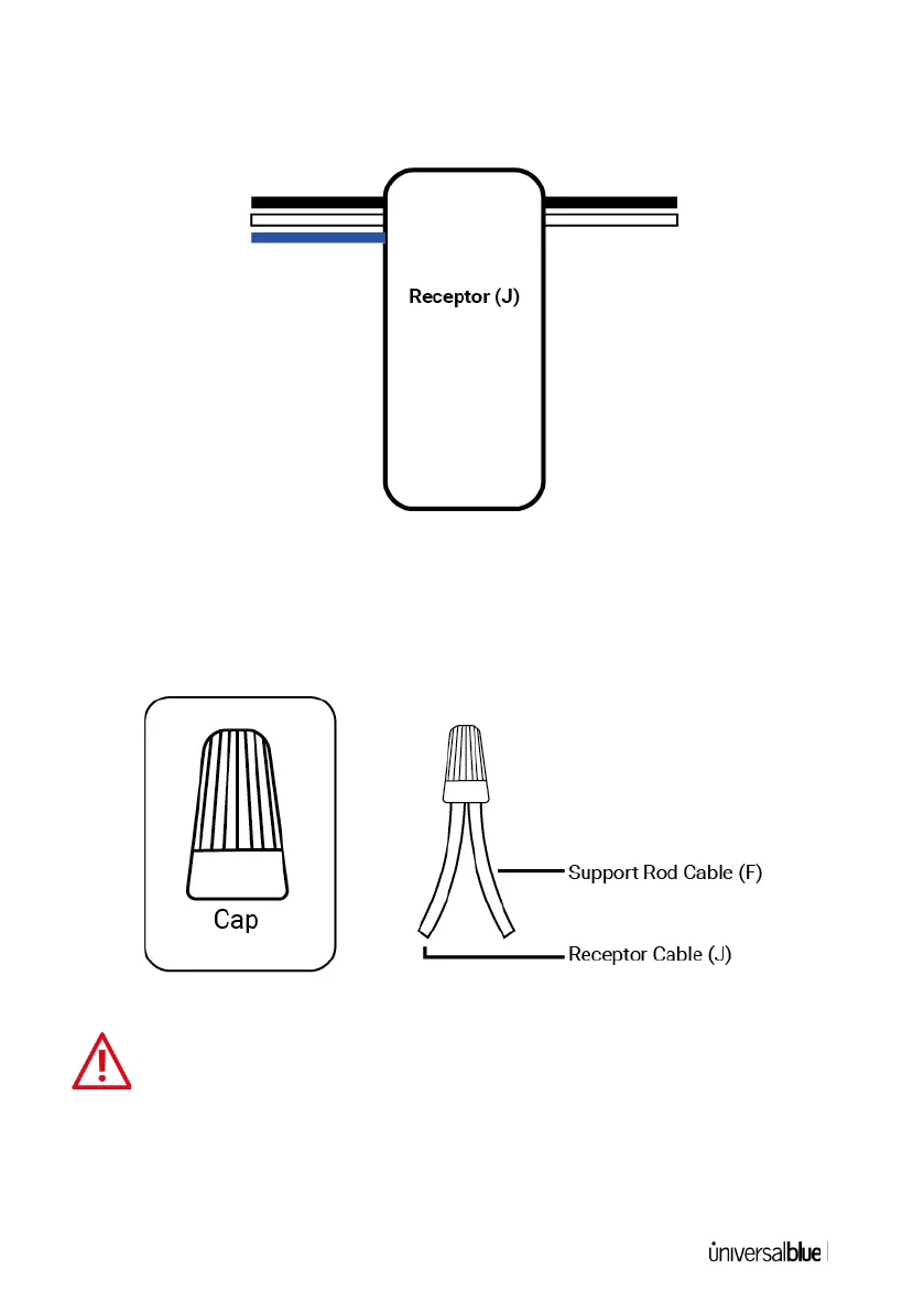
15. On the signal receptor (J) you will see 2 cables on one side of
the receiver and 3 cables protruding from the opposite side, as
shown in the image below:
16. The 3 cables coming out of the signal receptor (J) (white, black
and blue) must be connected with the cables coming out of the
support rod (F). Once the joint has been made, fix it with the
caps provided, as shown in the image below:
After making the connections between the cables, please
seal the joint with the caps included with this appliance, so
that the different cables do not touch each other with the fleuron or
other components.