

K
katelynwhiteheadAug 13, 2025
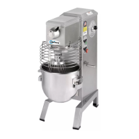
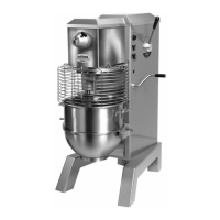
Why my Univex SRM60+ Mixer won't start?
- SShannon RobertsAug 13, 2025
Your Univex Mixer might not be starting due to several reasons: - There could be an electrical service issue. Check the electrical service and replace the fuse or reset the circuit breaker if needed. - The switch contacts might be burned. Consider replacing or cleaning them. - The timer might not be turned on. Ensure the timer is activated. - The motor capacitor could be defective (for 1PH models). Replace the capacitor. - The motor might be burned out. Remove, test, and repair or replace the motor. - The magnetic starter may have tripped due to an overload. Wait a few minutes and push the start button again. - The Safety Ring might not be properly mounted and closed. Install the Safety Ring correctly. - The bowl might not be raised completely. Make sure to raise the bowl fully.