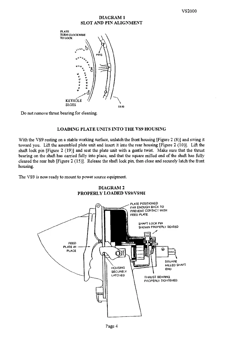
PIA1
TURN CLOCKWISE
TO LOCK
t,
a
)v
I
e'
t, I
vi
KEYHOLE
SLOTS
Do not remove thrust bearing for cleaning.
LOADING PLATE UNITS INTO THE VS9 HOUSING
With the VS9 resting on a stable working surface, unlatch the front housing [Figure 2 (8)] and swing it
toward you. Lift the assembled plate unit and insert it into the rear housing [Figure 2 (10)].
Lift the
shaft lock pin [Figure 2 (19)] and seat the plate unit with a gentle twist. Make sure that the thrust
bearing on the shafi has carried fully into place, and that the square milled end of the shaft has fully
cleared the rear hub [Figure 2 (15)]. Release the shaft lock pin, then close and securely latch the front
housing.
The VS9 is now ready to mount to power source equipment.
DIAGRAM 2
PROPERLY LOADED VS9/VS9H
Page 4
IItJB
PLATE POSITIONED
FAA ENOUGH BACK To
PREVENT CONTACT WITH
FEEO PLATE.
SHAFT LOCK PIN
SHOWN PROPERLY SEATED.
7
SQUARE
MILLED SHAFt
ENO
tHRUST BEARING
PROPERLY TIGHTENED.
VS2000
DIAGRAM i
SLOT AND PIN ALIGNMENT
PDF compression, OCR, web optimization using a watermarked evaluation copy of CVISION PDFCompressor

 Loading...