Picture 22 b
Treatment plant discharge and
overfl ow must be arranged so that no
backfl ow to the treatment plant can
occur. The overfl ow pipe ensures that
water cannot rise to the treatment
plant machine room. The pipes to be
joined are insulated if necessary, and
the pipe is slanted enough to prevent
water remaining in it (min. 1cm/m).
NOTE! Ensure the discharge location
does not freeze during winter!
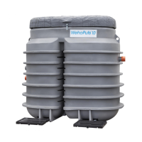
2.3.5 Assembling of ventilation
pipe and signal lamp
• Install the single branch in the
lower part of the ventilation
pipe.
• Pass the electrical cable of the
signal lamp trough the ventila-
tion pipe.
• Attach the signal lamp at the
end of the ventilation pipe and
lock it with a screw
(picture 22b).
• Install the ventilation pipe in
place and pass the cable to the
machine room.
• Connect the signal lamp plug
into the X7 socket.
2.3.6 Electrical connections
Electricity is connected to the treat-
ment plant as a fi xed land installation
from the property’s main distribution
board. The electrical cable is brought
to the machine room from the electri-
cal pass-through at the back of the
treatment plant. The cable should
be installed inside sand or protec-
tive tubing and marked according to
protection requirements.
The electricity cable is connected to
the single-phase socket in the treat-
ment plant machine room. The control
unit is connected to the socket with
a plug.
Treatment plant grounding is done
through the building’s main distribu-
tion board.
NOTE! Electrical cable connections
are to be carried out by a professional
electrician!
Electrical connections from the
property distribution board to
the treatment plant:
• 230V, 50Hz
• Distribution board main fuse
10A
• Electrical cable e.g. MCMK 2 x
1.5/1.5, if distance to treatment
plant is less than 100m
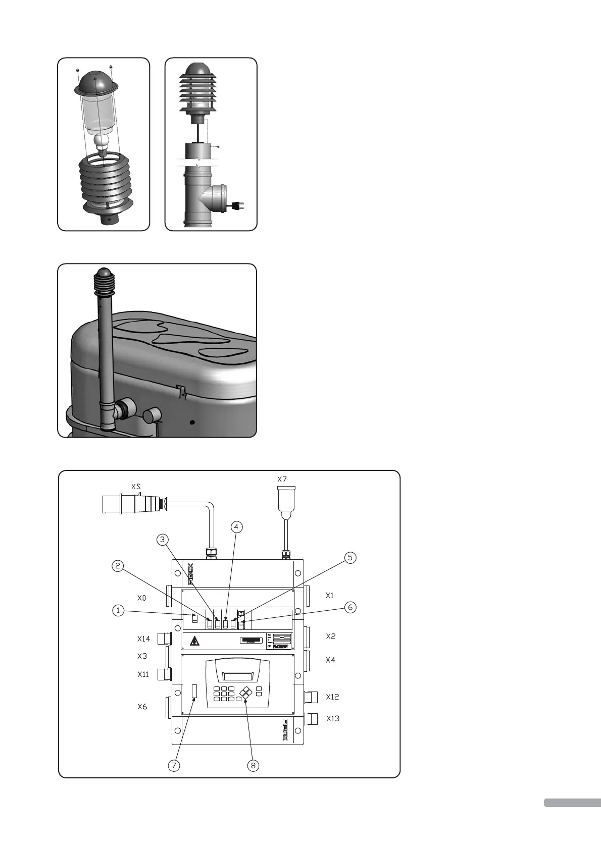
Control unit:
1 Main circuit breaker Q1
2 Main fuse F1 10A
3 Control fuse F2 2A
4 Pumps fuse F3 6A
5 Heater fuse F4 6A
6 Ground fault switch
F5 2B 25A 30mA
7 SIM card installation rail
for GSM modem (optional)
8 PLC-HMI
X0 Storage tank transfer pump P0
X14 Overfl ow level switch LS4
X3 Compressor P3
X11 Storage tank level switch LS1
X6 Service socket (heater, optional)
X1 Process tank emptying pump P1
X2 Chemical pump P2
X4 Process tank sludge pump P4
X12 Process tank level switch LS2
X13 Chemical tank level switch LS3
X7 Signal lamp H1
XS Control unit main plug
Electrical connection X6 is a process
control independent socket that
can be temporarily used e.g. during
service.
NOTE! Equipment not part of the
treatment plant must not be con-
nected to control unit!
11