9
DS1375-045
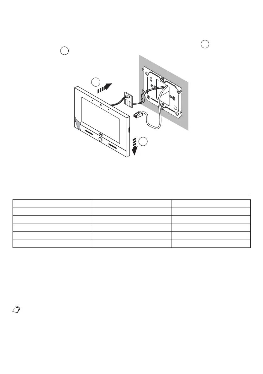
• Connectanypanicfunction,extraringtone,oorcall,auxiliarypowerfunctionwirestotheterminalson
the external printed circuit.
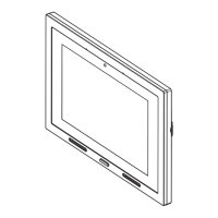
• Connect the video door phone to the connector CN1 on the printed circuit board via the cable provided
on the back of the video door phone.
• Movethevideodoorphoneclosetothebracketbycentringthespecialxings
1
and slide it down
to reach its stop
2
(see the following image).
1
2
• Use a screwdriver to move the latch for locking the video door phone to the bracket from left to right.
• Removetheprotectivelmfromthedisplay.
DISTANCES AND SECTIONS CABLES
Type of connection Max distance Min - max cross section
Calltooorlevel 30m 0,5-1mm
2
Panic Alarm 30m 0,5-1mm
2
Call repeating 30m 0,5-1mm
2
External power supply 25 m 0,5-1mm
2
LAN 100m CAT5e (*)
(*) To ensure longest-range video door phone operation, the cablemust be a class 5e device and the
twisted pairs’ cross section must be AWG24.
Themaximumresistanceoftheindividualwiresmustnotexceed10ohm/100m.
The cable must be up to the following standards:
-EIA/TIA568-B.2orEIA/TIA568-C.2
-EN502883-1
-IEC61156-5
The connection between the IP video door phone and POE switch must be ensured by a single cable
without any extra patch cords.
Wireswithcross-sectionareaof0.5mm2orlargermustcomplywithIEC60332-1-2;wireswith
crosssectionareasmallerthan0.5mm2mustcomplywithIEC60332-2-2.
 Loading...