8
DS1375-045
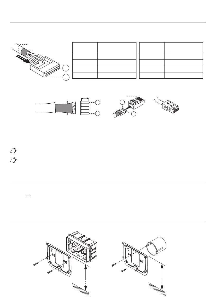
WIRING INSTRUCTIONS
With RJ45 Ethernet Cable connector
• Plug the cable into one of the RJ45 connectors with the Urmet logo.
• Insertthewireinitsguide,accordingtotheprovidedcolourcode(StandardT568B).
Black sheath
8
1
Wire
No.
Cable colour
1 White-Orange
2 Orange
3 White-Green
4 Blue
Wire
No.
Cable colour
5 White-Blue
6 Green
7 White-Brown
8 Brown
Grey sheath
• Cut the cables so that they protrude from the guide by about 5 mm, insert the guide in its plug and crimp
with the specially provided tool.
Plug
8
1
~ 5 mm
8
1
• Make sure that the grey sheath stays inside the plug.
• Connect one end of the Ethernet cable to the POE switch of the system and the other end to the LAN
connector of the device.
• Whenusingthelocalpowersupply,rstconnecttheLANcabletoanon-POE port on the switch and
then connect it to the local power supply.
ThistypeofconnectionwillNOTguaranteedoubleinsulation.
Forthemaximumdistancesandforthecongurationoperationsitisrecommendedtofollowthe
rulesprescribedintheiPerTAlkinstallationandcongurationbooklet.
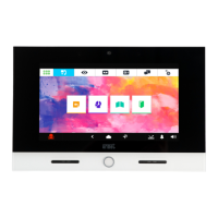
POWER SUPPLY
The1375/826IPvideodoorphonecanbesuppliedpowerintwodierentways:
— POE
— 48V
local power supply
When the power supply is used, POE is not available because the video door phone is powered only by the
local power supply. In this case, RJ45 can be connected to the NO POE port of the switch.
INSTALLATION
Itispossibletoxthewallbracketbyusinga503boxandthesuppliedscrews,oraØ60boxwithsuitable
screws.
1,50 m
Box
503
1,50 m
Box
Ø 60 mm
 Loading...