Do you have a question about the urmet domus Miwi 1131/521 and is the answer not in the manual?
Overview of the system's fundamental capabilities and characteristics.
Guidelines for connecting wires, including cross-sections and distances.
General advice for making electrical connections in the system.
Describes how to set up the system with a single entrance panel.
Details configuration for systems with multiple main entrance panels.
Explains the Master/Slave architecture for complex installations.
Guide for installing video doorphones with a single entrance panel.
Instructions for video doorphone systems with multiple entrance panels.
Activating relays using general opening codes for external devices.
Instructions for resetting the power supply unit.
Activating relays using individual opening codes for external devices.
Method to access programming mode in case of password loss.
Default configuration for user codes in the system.
How to initiate calls to users within the system.
Using general codes to open doors.
Using individual codes to open doors.
Overview of the system's programming mode and its structure.
Setting the mode for general opening codes.
Functions for deleting various types of system data.
Main setup parameters including password, module ID, and sound level.
Advanced settings including backlight, switchboard, and EXI terminal configuration.
Core setup parameters for the system.
Setting the mode for individual opening codes.
Deleting all logical user codes for SLAVE devices.
Settings for various time-related parameters like calling and conversation.
Configuration settings for Master/Slave power supply units.
Procedure to edit or change the system's access password.
Modifying the function of the relay linked to the electrical lock.
Deleting all individual opening codes from the system.
Functions for deleting various types of system data.
How to modify the identification number of a call module.
Setting the voltage level for the door phone line.
Deleting all general opening codes from the system.
Restoring default settings for different system parameters.
Setting automatic confirmation for user codes.
Configuration of various time-related parameters.
Deleting all logical user codes for MASTER devices.
Settings related to LU line configuration.
Programming and management of logical user and opening codes.
Configuring confirmation signals for personal opening codes.
Setting the duration the electrical lock remains active.
Deleting all Dallas keys from the system.
Using Dallas keys for door opening and system control.
Configuring the duration of the calling signal.
Deleting all data related to the digitizer.
Defining whether to use logical or physical user codes.
Setting the maximum time for picking up the handset.
Comprehensive data deletion for multiple system components.
Defining the maximum duration for a conversation.
Restoring default settings for various system parameters.
Setting the activation time for the NC-C-NO relay.
Restoring logical user codes with range limitations.
Restoring individual opening codes to their default states.
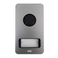
Features and construction of the 1752/11..11D camera call module.
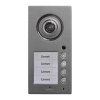
Features and construction of the 1752/16..16D camera call module.
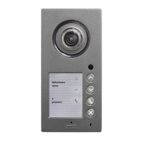
Features and structure of the Sinthesi call module with keyboard.
Overview of basic system functions supported by the module.
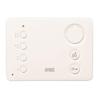
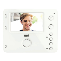
Features of the 1131/521 house phone with an additional button.
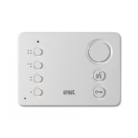
Features of the 1132/521 house phone with an additional button.
Features and specifications of the Video Power Supply unit.
Features and description of the 4-output decoder.
Features and description of the digitiser.
Key features of the switchboard station for Matibus SE systems.
Technical specifications for the switchboard station.
| Brand | Urmet Domus |
|---|---|
| Colour | White |
| Model | 1131/521 |
| Display | LCD |
| Housing Material | Plastic |