EasyManua.ls Logo

urmet domus Miwi Matibus SE User Manual

urmet domus Miwi Matibus SE
98 pages
To Next Page IconTo Next Page
Page #1 background imageLoading...
Page #1 background image
1
DIGITAL CALL SYSTEM

Table of Contents

Question and Answer IconNeed help?

Do you have a question about the urmet domus Miwi Matibus SE and is the answer not in the manual?

urmet domus Miwi Matibus SE Specifications

General IconGeneral
Brandurmet domus
ModelMiwi Matibus SE
CategoryIntercom System
LanguageEnglish

Summary

Introduction to Matibus SE System

Basic Features of Matibus SE

Describes core functionalities of the digital call system.

System Installation Parameters

Details parameters for system setup and configuration.

Wiring Specifications

Outlines wire types and cross-sections for installation.

Electrical Connections Overview

Provides basic guidance on electrical connections.

Installation Types and Configurations

Single Entrance Panel Installation

Describes setup with one entrance panel.

Multiple Entrance Panel Installations

Covers systems with several entrance panels.

Video Doorphone Installation Types

Details video system installation scenarios.

Call Module Technical Details

Call Module REF. 1052/10 & 1052/11 Specifications

Features, construction, and specs for specific models.

Call Module REF. 1052/15 & 1052/16 Specifications

Features, construction, and specs for specific models.

System Operation Instructions

Terminal Board Description and Basic Functions

Explains terminals and core system functions.

System Maintenance and Programming Access

Covers serial numbers, reset, and emergency programming.

Programming Mode Overview

Introduces programming structure and modes.

Relay Activation and Terminal Functions

Details specific operational functions like relay control.

Programming Mode Configuration

System Setup and Parameter Configuration

Covers main setup, LU line, time, advanced functions.

Data Management and Deletion Procedures

Covers data deletion, restore, services.

User Code and Opening Code Management

Covers remapping, individual, general, and Dallas key codes.

Programming Mode Advanced Settings

Dallas Key Operations and Service Functions

Key management and service information.

Software Version and Advanced Features

Software info and backlight, switchboard settings.

Master/Slave Configuration

Settings for master/slave power supplies.

System Improvement Features and Updates

Communication modes, resets, updates.

Errors Report and Module Adjustment

Error Codes and Explanations

Identifies and explains system error codes.

Module Adjustment Procedures

Steps for fine-tuning module performance.

Activating the System

Master System Activation Process

Steps for initial setup of the master unit.

Master/Slave System Activation Process

Steps for setting up master/slave configurations.

Mounting Panels Installation

Panels REF. 1052/10 & 1052/15 Installation

Guide for installing specific panel models.

Panels REF. 1052/11 & 1052/16 Installation

Guide for installing specific panel models.

Call Module with Camera Technical Details

REF. 1752/11 Basic Features and Construction

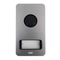
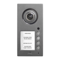
Details for the 1752/11 camera module.

REF. 1752/16 Basic Features and Construction

Details for the 1752/16 camera module.

Technical Specifications for Camera Modules

Operation and Programming Instructions

How to operate and program camera modules.

Terminal Board Descriptions

Explanation of module terminals.

Video Terminal Connections

Details on video signal connections.

Mounting Panels REF. 1752/11 & 1752/16

Assembly Name Tags

Instructions for applying name tags.

Wall and Flush-Mounted Installation

Installation methods for camera modules.

Sinthesi Call Module REF. 1052/13 Details

Basic Features

Core functionalities of the Sinthesi module.

Basic System Functions

Fundamental system operations.

Module Structure

Description of the module's physical components.

Operation Instructions for Sinthesi Module

Serial Numbers and Emergency Programming Access

System maintenance and recovery.

Programming Mode Access and Structure

How to enter and navigate programming.

Relay Activation and Terminal Functions

Specific operational controls and terminals.

Programming Mode Configuration Overview

System Setup and Parameter Configuration

Covers main setup, LU line, time, advanced functions.

Data Management and Deletion Procedures

Covers data deletion, restore, services.

User Code and Key Management

Covers remapping, individual, general, and Dallas key codes.

Advanced Settings and Master/Slave Configuration

Covers various settings like frequency, voltage, master/slave.

System Features and Updates

Communication modes, resets, and software updates.

Errors Report and Module Adjustment

Error Codes and Troubleshooting

Identifies and explains system error codes.

Module Adjustment Procedures

Steps for fine-tuning module performance.

Activating the System

Master System Activation Process

Steps for initial setup of the master unit.

Master/Slave System Activation Process

Steps for setting up master/slave configurations.

Installation Guide for Entrance Panels

General Installation Notes

Important considerations for panel installation.

Flush-Mounted Installation Variations

Methods for flush mounting panels.

Wall-Mounted Installation Variations

Methods for wall mounting panels.

House Phone REF. 1131/520 Details

Basic Features and System Connection

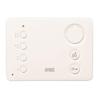
Core functions and how to connect the phone.

Terminal Board Description

Explanation of the phone's terminals.

Programming and Volume Adjustment

How to configure the phone and adjust volume.

House Phone REF. 1131/521 Features

Basic Features

Core functionalities of the 1131/521 model.

Table-Top Mounting Kit REF. 1130/120 Features

Basic Features

Information on the mounting kit.

House Phone REF. 1132/520 Details

Basic Features and System Connection

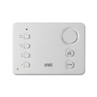
Core functions and connection for the 1132/520 model.

Terminal Board Description

Explanation of the 1132/520 terminals.

Programming and Volume Adjustment

Configuration and volume settings for the 1132/520.

House Phone REF. 1132/521 Features

Basic Features

Core functionalities of the 1132/521 model.

Table-Top Mounting Kit REF. 1332/51 Features

Basic Features

Information on the mounting kit.

House Phone REF. 1132/620 Details

Basic Features and System Connection

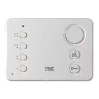
Core functions and connection for the 1132/620 model.

Terminal Board Description

Explanation of the 1132/620 terminals.

Programming and Volume Adjustment

Configuration and volume settings for the 1132/620.

House Phone REF. 1132/621 Features

Basic Features

Core functionalities of the 1132/621 model.

Video Door Phone WINFLAT REF. 1202/1A Details

Basic Features

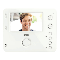
Key characteristics of the WINFLAT video door phone.

Connection to the System

How to connect the WINFLAT unit.

Winflat Bracket REF. 1202/952 Configuration

Basic Features

Core information about the bracket.

Terminal Board Description

Explanation of the bracket's terminals.

Bracket Configuration Details

Specific settings for the bracket.

Video Line UTP Termination

Setting for UTP video line termination.

Bracket Configuration Operation

Video Audio-On Function

How to activate video auto-on.

Switchboard Call and OC Control

Functions for switchboard and OC control.

Door Opening and Floor Call

Features for door release and floor calls.

Calling Tone and Video Signal Detection

Settings for call tones and video signal.

Technical Specification

Technical details of the bracket.

Power Supply "MASTER" REF. 1052/31A Details

Terminal Board Description

Explanation of the power supply's terminals.

Basic Features

Core functionalities of the master power supply.

Construction and Diagnostics

Physical aspects and status indicators.

Configuration and Technical Specification

System setup and technical data.

Power Supply "Master/Slave" REF. 1052/33 Details

Terminal Board Description

Explanation of the power supply's terminals.

Basic Features

Core functionalities of the master/slave power supply.

Construction and Diagnostics

Physical aspects and status indicators.

Configuration and Technical Specification

System setup and technical data.

Additional Power Supply REF. 1052/20 Details

Basic Features and Terminal Description

Core functions and terminals of the additional supply.

Technical Specification

Technical data for the additional supply.

Video Power Supply REF. 789/7P Details

Basic Features

Core functions of the video power supply.

Technical Specification

Technical data for the video power supply.

Video Distributor REF. 1752/54 Operation

General Information

Overview of the video distributor's purpose.

Terminal Board Description

Explanation of the distributor's terminals.

Programming Procedure

Steps for programming the distributor.

Video Distributor REF. 1794/4 SID Details

Basic Features

Core functionalities of the distributor.

Description of Terminals

Explanation of the distributor's terminals.

Relay Switch REF. 1032/9 Features

Basic Features

Core functions of the relay switch.

Terminal Description

Explanation of the switch's terminals.

Technical Specification

Technical data for the relay switch.

4 Outputs Decoder REF. 1052/34 Details

Basic Features

Core functionalities of the decoder.

Terminal Description

Explanation of the decoder's terminals.

Physical Address Settings

How to configure decoder addresses.

Switchboard Call or OC Control

Control functions via switchboard.

Digitiser REF. 1052/7 Details

Basic Features

Core functionalities of the digitiser.

Construction

Physical assembly of the digitiser.

Terminal Board Description

Explanation of the digitiser's terminals.

Technical Specification

Technical data for the digitiser.

Digitiser REF. 1052/7 Programming

ID Setting Configuration

How to set the digitiser's unique ID.

Digitiser Group Settings

Configuration for grouping multiple digitizers.

Digitiser REF. 1052/7 Configuration

Button Programming and Calling

Using buttons for programming and calls.

Configuration and Adjustment Procedures

General setup and potentiometer adjustments.

Operation Instructions

How to operate the digitiser.

Switchboard Station REF. 1052/40 Details

Basic Features

Core functionalities of the switchboard.

Construction and Pin Assignments

Physical layout and connector details.

Switchboard Station REF. 1052/40 Configuration

Technical Specification

Technical data for the switchboard.

Panel ID and Name Editing

How to modify panel identification.

Editing Entrance Panel Names

Procedure for naming entrance panels.

Switchboard Station REF. 1052/40 Configuration

Relay Outputs and Time Settings

Configuring relays and time parameters.

Password, Sound, and Language Settings

Personalizing the switchboard.

Day/Night Service and Software Version

Service modes and software information.

Switchboard Station REF. 1052/40 Configuration

Restoring Default Settings

Procedure to reset the switchboard to factory defaults.

Switchboard Station REF. 1052/40 Operation

Functional Keys Overview

Description of the switchboard's keys.

Calling from Door Phone

How to initiate calls from door phones.

Calling from Entrance Panel

How to initiate calls from entrance panels.

Switchboard Station REF. 1052/40 Operation

Door Phone Calling and Hands-Free Mode

Managing calls and hands-free operation.

Day/Night Service and Call Storage

Service modes and call logging.

Switchboard Station REF. 1052/40 Operation

Repertory Management

Adding, modifying, and managing user contacts.

User and Lock Functions

Controlling door locks and relay functions.

Switchboard Station REF. 1052/40 Adjustment

Error Reporting

Understanding and resolving system errors.

Adjustment Procedures

Steps for fine-tuning the switchboard station.

Diagrams

One Main Audio Entrance Panel Diagram

Wiring diagram for a single audio panel.

One Main Audio Entrance Panel (Extended Version) Diagram

Wiring diagram for an extended audio panel.

Three Main Audio Entrance Panels (UTP) Diagram

Wiring diagram for a UTP audio system.

Decoder REF. 1052/34 (UTP) Diagram

Wiring diagram for a UTP decoder.

Diagrams

One Video Entrance Panel (Coax Version) Diagram

Wiring diagram for a coax video panel.

One Video Entrance Panel (Coax with Distributors) Diagram

Wiring diagram for a coax video system with distributors.

One Video Entrance Panel (UTP Version) Diagram

Wiring diagram for a UTP video panel.

Decoder REF. 1052/34 (UTP) Diagram

Wiring diagram for a UTP decoder.

Diagrams

Three Video Entrance Panels (UTP) Diagram

Wiring diagram for a UTP video system.

Decoder REF. 1052/34 (UTP) Diagram

Wiring diagram for a UTP decoder.

Decoder REF. 1052/34 (UTP) Diagram

Wiring diagram for a UTP decoder.

One Analogue Entrance Panel (System with Digitalizer) Diagram

Wiring for an analogue system with digitalizer.

Diagrams

Three Analogue Entrance Panels (System with Digitalizers) Diagram

Wiring for a multi-analogue system with digitalizers.

Dip-Switch and Jumpers Settings

Table of Video Bracket Settings

Settings for video bracket dip-switches.

Table of Door Phone Settings

Settings for door phone jumpers.

Digitizer Settings

Settings for digitizer dip-switches.

Notes

General Notes

Additional remarks.

Related product manuals