EasyManua.ls Logo

urmet domus Miwi 1132/520 User Manual

urmet domus Miwi 1132/520
98 pages
To Next Page IconTo Next Page
Page #1 background imageLoading...
Page #1 background image
1
DIGITAL CALL SYSTEM

Table of Contents

Question and Answer IconNeed help?

Do you have a question about the urmet domus Miwi 1132/520 and is the answer not in the manual?

urmet domus Miwi 1132/520 Specifications

General IconGeneral
TypeVideo Intercom
ModelMiwi 1132/520
Wiring2-wire
Resolution480 x 272 pixels
CameraYes
Power ConsumptionMax 5W
AudioFull-duplex
InstallationSurface mounted
Night VisionYes, with IR LEDs

Summary

Introduction to Matibus SE System

Electrical Connection Guidelines

Guidance on electrical connections for the system.

Installation Types

Single Entrance Panel Installation

Diagram for installing with one entrance panel.

Multiple Main Entrance Panels Installation

Diagram for installing with multiple main entrance panels.

Master/Slave Architecture Installation

Diagram for Master/Slave architecture installations.

Video Doorphone Installation Types

Single Entrance Panel Video Installation

Diagram for video doorphone installation with one panel.

Multiple Entrance Panels Video Installation

Diagram for video doorphone installation with multiple panels.

Call Module with Keyboard: Model 1052 Series

Basic Features of 1052/10..10D

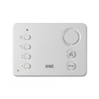
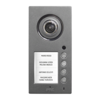
Core features of the 1052/10..10D call module.

Technical Specification for 1052/10..10D

Technical specifications for the 1052/10..10D call module.

Basic Features of 1052/11..11D

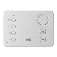
Core features of the 1052/11..11D call module.

Technical Specification for 1052/11..11D

Technical specifications for the 1052/11..11D call module.

Call Module with Keyboard: Models 1052/15 & 1052/16

Basic Features of 1052/15..15D

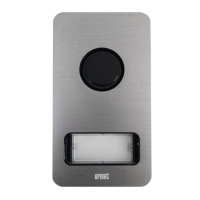
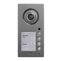
Core features of the 1052/15..15D call module.

Technical Specification for 1052/15..15D

Technical specifications for the 1052/15..15D call module.

Basic Features of 1052/16..16D

Core features of the 1052/16..16D call module.

Technical Specification for 1052/16..16D

Technical specifications for the 1052/16..16D call module.

Operation Instructions for Matibus SE System

Programming Mode Instructions

Dallas Key Operation for Door Opening

Using Dallas keys for door opening.

Programming Mode Settings and Navigation

Default settings and structure of the programming menu.

Programming Mode Menu Structure

System Parameters and Setup

Main Setup Options

Main setup options including password and module ID.

Edit Call Module ID

Changing the identification ID of the call module.

Programming Mode Settings

Data Management and Settings Restore

Settings Restoration and Code Management

User Code Mapping and Programming

Dallas Key Management and Service Functions

System Maintenance and Advanced Functions

Advanced Programming Functions

Master/Slave Configuration and User Codes

System Configuration and Features

Additional Channel and System Improvements

Automatic Master Power Supply Selection

Enabling/disabling automatic MASTER power supply selection.

Power Supply Reset Procedure

Resetting the power supply.

Error Reporting and Module Adjustment

Call Module Adjustment (1052 Series)

Pre-adjustment and potentiometer functions for call modules.

Call Module Adjustment (1052/13)

Pre-adjustment and potentiometer functions for call module 1052/13.

Error Codes Report

Table listing error codes and their explanations.

System Activation Procedures

Master System Activation

Step-by-step guide for activating the MASTER system.

Master System Activation Steps

Step-by-step guide for activating the MASTER system.

Master/Slave System Activation

Activation steps for MASTER/SLAVE systems.

Master/Slave System Activation Steps

Activation steps for MASTER/SLAVE systems.

Panel Mounting Instructions

Panel Mounting Procedures for 1052/11 & 1052/16 Series

Camera Call Module Features and Construction

Video Module Technical Specifications

Operation and Programming Instructions

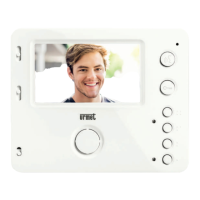
Instructions for operating and programming video modules.

Panel Mounting for 1752/11 & 16 Series

Sinthesi Call Module Model 1052/13

Operation Instructions for Switchboard Station

Emergency Programming Mode Entry

Method to enter programming mode without password.

User Code Default Settings

Default configuration for user codes.

Calling System Users

How to call users within the system.

Using General Opening Codes

Using general codes to open doors.

Using Individual Opening Codes

Using individual codes to open doors.

Switchboard Station Operation and Programming

Programming Mode Overview

Overview of the programming mode.

NC-C-NO Relay Activation with General Codes

Using general codes to activate NC-C-NO relay.

NC-C-NO Relay Activation with Individual Codes

Using individual codes to activate NC-C-NO relay.

Programming Mode Settings Overview

Default settings and structure of the programming menu.

Entering the Programming Mode

Steps to enter the programming mode.

Programming Menu Structure

Structure and navigation of the programming menu.

Programming Mode Menu Options

Main Setup (P0XX)

Main setup options including password and module ID.

Logical User and Opening Codes (P5XX)

Managing logical user and opening codes.

Master/Slave Functions (P8XX)

Configuration for Master/Slave power supply setup.

Programming Mode Functionality

How to navigate and use the programming mode.

System Setup Parameters

Main Setup: Edit and Change Password

Process to edit and change the system password.

Main Setup: Edit Call Module ID

Changing the identification ID of the call module.

Programming Mode: Codes and Time Settings

Data Deletion Procedures

Settings Restoration Procedures

EEPROM Memory Deleting and Reset

Resetting EEPROM memory and programming steps.

Logical User Codes Programming

Programming logical user codes for house phones.

User Code Management and Dallas Keys

Re-mapping Logical User Codes

Reprogramming logical user codes.

Individual Opening Codes Programming

Programming individual opening codes for users.

General Opening Codes Programming

Programming general opening codes for keyboards.

Dallas Key Programming

Assigning Dallas keys to user codes.

Dallas Key Operations and Service Functions

Dallas Key Programming Procedure

Assigning Dallas keys to user codes.

Software Versions and Advanced Functions

Advanced Programming and System Settings

Electrical Lock Modes and Master/Slave Setup

Master Power Supply ID Change

Changing the ID number of the MASTER power supply.

Logical User Codes Programming (Main Channel)

Programming logical user codes for the main channel.

Re-mapping Logical User Codes (Main Channel)

Re-mapping logical user codes for the main channel.

Call Module Installation

Panel Mounting Options

House Phone Model 1131/520

Programming Address for 1131/520

Setting the house phone's physical address via jumpers.

House Phone Model 1131/521 and Mounting Kit

House Phone Model 1132/520

Programming Address for 1132/520

Setting the house phone's physical address via jumpers.

House Phone Models 1132/520, 1132/521 & Mounting Kit

House Phone Model 1132/620 Specifications

Programming Address for 1132/620

Setting the house phone's physical address via jumpers.

House Phone Model 1132/621 Basic Features

Video Door Phone Winflat Model 1202/1A

Winflat Bracket Configuration

Bracket Dipswitch and Terminal Settings

Dipswitch settings for physical address and video line termination.

Bracket Operation and Technical Specifications

Bracket Technical Specifications

Technical specifications for the bracket.

Master Power Supply Model 1052/31A

Master Power Supply Technical Specifications

Technical specifications for the Master power supply.

Master/Slave Power Supply Model 1052/33

Master/Slave Power Supply Technical Specifications

Technical specifications for the Master/Slave power supply.

Additional and Video Power Supplies

Additional Power Supply 1052/20 Technical Specs

Technical specifications for the additional power supply.

Video Power Supply 789/7P Technical Specs

Technical specifications for the video power supply.

Video Distributor Model 1752/54

Video Distributor Programming Procedure

Procedure for programming the video distributor.

Video Distributor Model 1794/4 SID

Relay Switch for Video Systems

Relay Switch Technical Specifications

Technical specifications for the relay switch.

4 Outputs Decoder Model 1052/34

Physical Address Settings for Decoder

Programming physical addresses using dipswitches.

Digitiser Model 1052/7

Digitiser Technical Specifications

Technical specifications for the digitiser.

Digitiser Programming and Settings

Digitiser ID Setting Procedure

Setting the unique ID for each digitiser.

Digitiser Programming and Configuration

Button Programming for Door Phones

Associating buttons with door phones and setting power unit.

Switchboard Station Model 1052/40 Features

Switchboard Station Configuration

Switchboard Station Configuration Menu

Configuration menu for the switchboard station.

Editing Entrance Panel Names

Assigning names or descriptions to entrance panels.

Switchboard Station Configuration Options

Access Password Programming

Setting and managing the access password.

Switchboard Station Default Settings

Switchboard Station Operation Instructions

Switchboard Station Operating Procedures

Switchboard Station Repertory Management

Repertory Operations

Managing the user repertory.

Repertory Editing Procedures

Procedures for editing the repertory.

Adding New Users to Repertory

Steps to add a new user to the repertory.

Modifying User Entries in Repertory

Modifying existing user entries in the repertory.

Switchboard Station Adjustment and Error Reporting

Switchboard Station Adjustment Options

Adjusting switchboard station parameters like display contrast and volume.

Error Reporting and Interpretation

Reporting and interpreting system errors.

Wiring Diagrams: Single Main Audio Panel

Wiring Diagrams: Extended Main Audio Panel

Wiring Diagrams: Three Main Audio Panels

Wiring Diagrams: Main and Additional Panels

Wiring Diagrams: Master/Slave with Switchboard

Wiring Diagrams: Single Video Panel (Coax)

Wiring Diagrams: Video Panels with Coax Distributors

Wiring Diagrams: Single Video Panel (UTP)

Wiring Diagrams: Video Panels with UTP Distributors

Wiring Diagrams: Three Video Panels with UTP Distributors

Wiring Diagrams: Decoder with UTP Distributors

Wiring Diagrams: Decoder 1052/34 with UTP Distributors

Wiring Diagrams: Analogue Panel with Digitiser

Wiring Diagrams: Three Analogue Panels with Digitisers

Dip-Switch and Jumpers Settings for Video Brackets

Table of Video Bracket Settings

Table showing dip-switch and jumper settings for video brackets.

Dip-Switch and Jumpers Settings for Digitisers

Digitiser Settings Table

Table of dip-switch and jumper settings for digitisers.

Related product manuals