TECHNICAL SPECIFICATION
OPERATION AND PROGRAMMING INSTRUCTION
http://www.miwiurmet.com.pl e-mail:miwi@miwiurmet.com.pl
29
TECHNICAL SPECIFICATION
Power supply voltage
~ 12 V AC
or
+ 20 V DC
Driving of electrical lock
-with build in three state regulation
of current U
max
=12V
-NO–C–NC maximum value 1A/24V
DC
0L LG line voltage + 7,5…12,5 V DC
0L D line voltage + 15 V DC nom.
Operating temperature
-20°C ÷ +50°C
Size (high x width x
deep.)
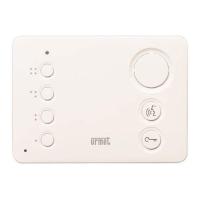
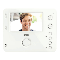
152 x 163 x 23mm (ref. no.1052/11)
Size (high x width x
deep.)
152 x 163 x 23-35mm
(ref. no. 1052/11D)
Size (high x width x
deep.)
175 x 188 x 23.6mm
(with frame 525/RP3)
DESCRIPTION OF TERMINAL BOARDS
LG Voice line
0L GND.
D Data line.
R Additional control terminal for video version
GND Contacts input/output ground.
+V Input voltage + 15…+20 V DC.
AC1 Input voltage ~12 V AC.
AC2 Input voltage ~12 V AC.
+CL Electric lock output (+).
-CL Electric lock output (-).
NC Relay normally closed contact.
C Relay Common contact.
NO Relay normally open contact.
PH Door lock release.
GND Contacts input/output ground.
EXI Contact input- door sensor input.
X1 Microphone socket.
X2 Speaker socket.
X12 Backlight information module power socket
X10 Dallas key reader socket.
VIDEO TERMINAL
+R Camera power positive input +18 V DC
TR Camera on control (+).
R Camera on control (-).
A/V3 Video signal output (core of coax or channel A).
B/V5 Video signal output (shield of coax or channel B).
R1 Camera power negative.
OPERATION AND PROGRAMMING
INSTRUCTION
To choose kind of transmission video signal please use
dip-switches S1 and S2.
• Set both dip-switches S1 and S2 in A-B position to use UTP
cable for video transmission (transmission in differential way)
• Set both dip-switches S1 and S2 in V3-V5 position to use
Coaxial cable for video transmission.
• Operation and programming instructions are the same as
instructions for 1052/10..10D and 1052/11D.

 Loading...


