3-537.1 95-8533
Supervised Output for Deluge and Pre-action
Connect external wiring to the appropriate terminals
on the terminal block. See Figure 3-67. Wire one or
more releasing devices to the module output.
The output of the Agent Release Module supervises
the releasing circuit via the coil of the releasing
solenoid. It is essential to use a releasing device
approved for use with this output module.
NOTE
This type of output does not require the use of
EOL resistors or diodes to supervise the circuit.
The output can be configured for latching, continuous
or timed response.
To ensure proper operating voltage, the input voltage
to the release module must be in the range from 21 to
30 vdc and the maximum wiring length must not
exceed the values shown in Table 3-20 for deluge and
pre-action applicati ons. Pe r FM Approval
requirements, the secondary power must provide
capacity for a 90 hour minimum standby operation
followed by a minimum of 10 minutes of releasing and
alarm operation. The initiating device circuit(s) for
use with the deluge and pre-action system
conguration must be wired within 20 feet and in
conduit from an IDC or DCIO. In addition, power for
the device(s) must be per NFPA 72 Class A wiring
techniques.
NOTE
In EQP systems with EQP2120PS(–B) Power
Supplies, the secondary power is customer
supplied and must be accepted by the Authority
Having Jurisdiction (AHJ).
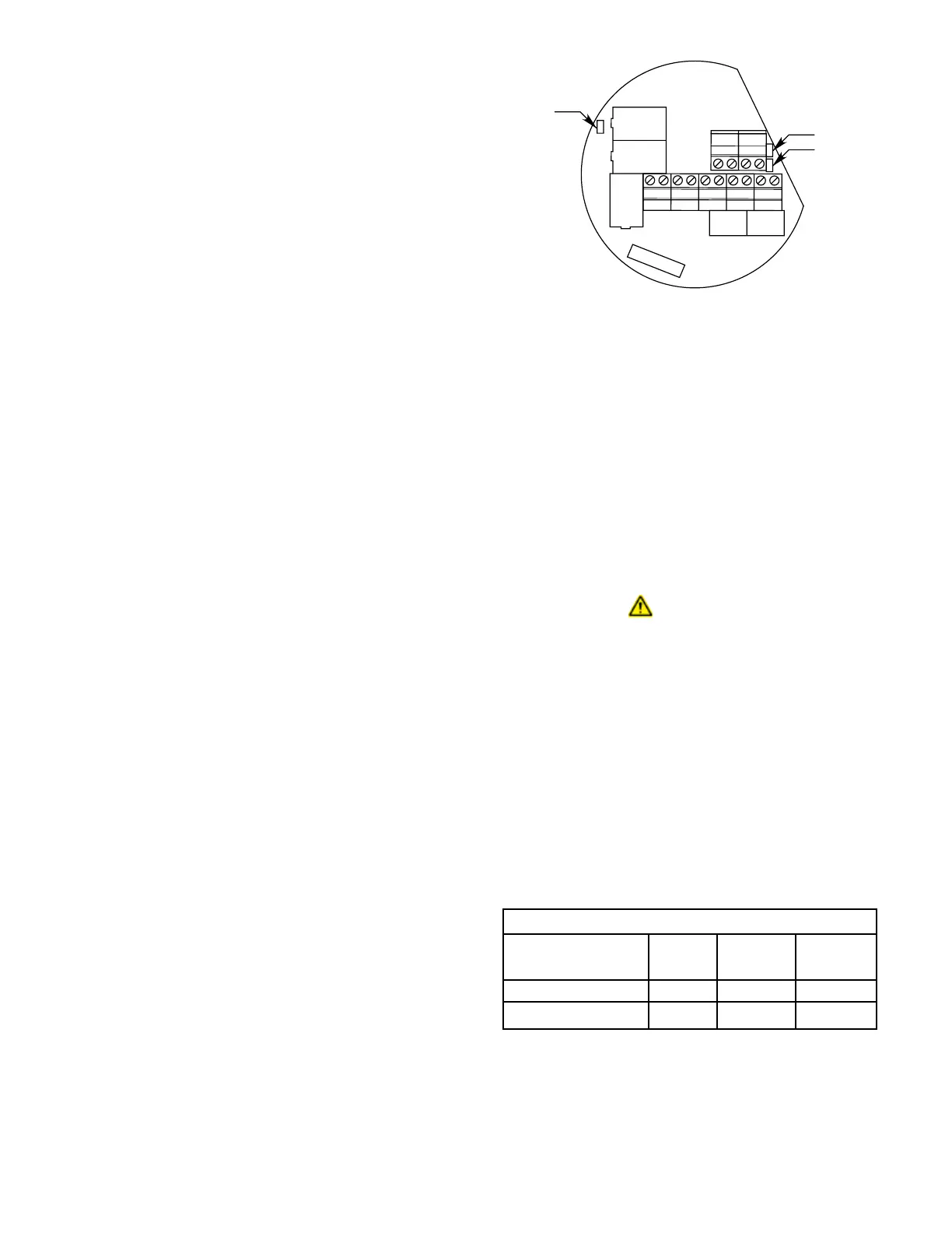
Jumpers
Terminals 13 and 14 are connected by jumper JP2
and terminals 11 and 12 are connected by jumper
JP3. These two jumpers (JP2 and JP3) must be cut if
an auxiliary output power supply is being used. (See
Figure 3-68 for jumper locations.)
When an explosive initiator is being used, jumper JP1
must be cut. If a solenoid is used, the jumper must
remain in.
Address Setting
Set the device network address. (See “Setting Device
Network Addresses” in this section.)
EQ25XXSAM SERIES SIGNAL AUDIBLE MODULE
Mounting
The device should be securely mounted to a vibration
free surface. (See “Specifications” in this manual for
device dimensions.)
Wiring
IMPORTANT!
To ensure adequate operating voltage for the
signaling device, the maximum wiring length
from the power source to the output device must
not exceed the values shown in Table 3-21. (This
wire length includes both the wiring from the
power supply to the signal audible module and
the wiring from the module to the signaling
device.)
See Figure 3-69 for identification of wiring terminals.
910
78
56
34
12
13 14
11 12
JP1
JP2
JP3
A1902
Figure 3-68—Agent Release Module Wiring Terminals and Jumpers
Maximum Wire Length in Feet (Meters)
12 AWG 14 AWG 16 AWG
(4 mm
2
)* (2.5 mm
2
)* (1.5 mm
2
)*
One 2 Ampere Load 190 (58) 120 (37) 75 (23)
Two 2 Ampere Loads 95 (29) 60 (18) 35 (11)
T0029A
* Approximate Metric Equivalent.
Table 3-21—Maximum Wiring Length
from Nominal 24 VDC Power Source to Signaling Device
 Loading...