7.1 95-85332-3
Controller based fault conditions include the Controller
status and LON communications such as the
heartbeat being sent around the loop and the field
device loss of communications. Controller based fault
conditions are listed in Table 2-1.
Field device based fault conditions are transmitted to
the Controller, where they are then annunciated. Refer
to Table 2-2 for a listing of field device faults. Each
field device transmits its status to the Controller
on a regular basis.
When an alarm condition occurs, the Controller
displays the alarm condition on the text display,
activates the appropriate Alarm LED(s), and activates
the alarm signal using the Controller’s internal
annunciator.
Each field device must communicate alarm and fault
conditions to the Controller. The timing for transmitting
alarms and faults to the Controller is displayed in
Table 2-3.
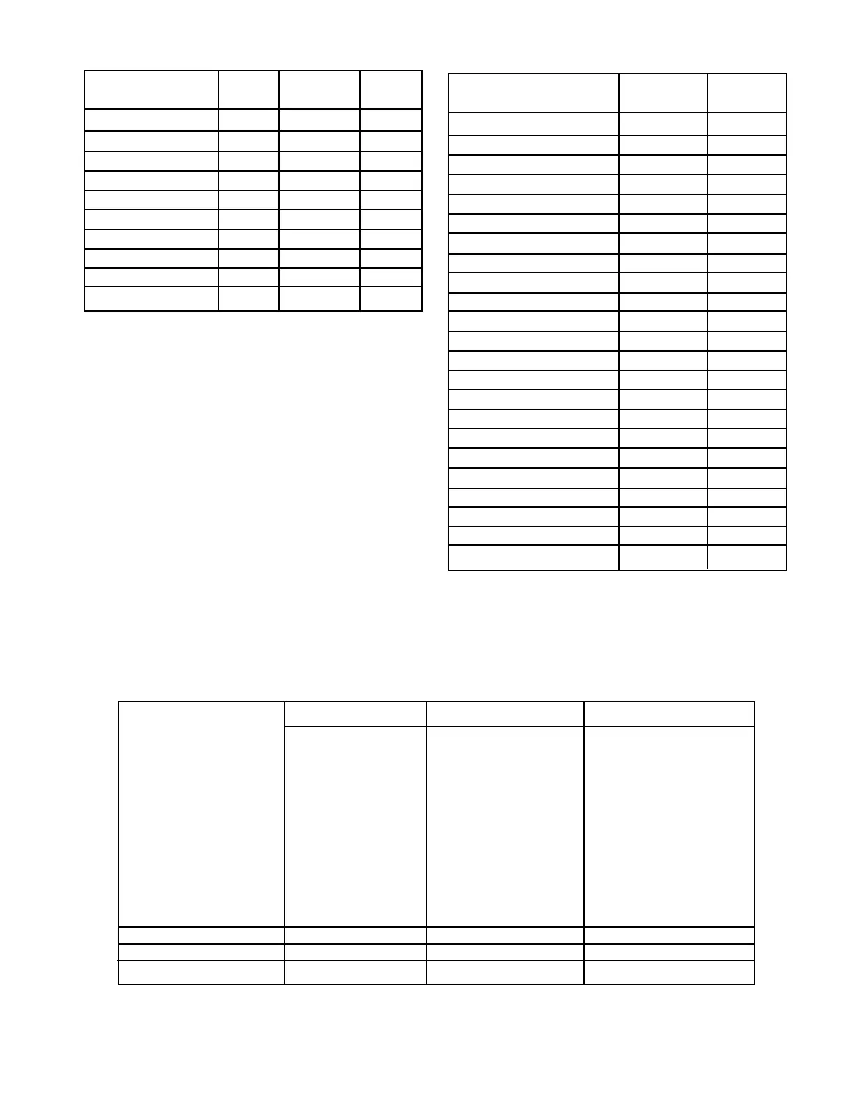
Controller Faults Trouble LON Fault Trouble
Shown on Text Display LED LED Relay
Controller Fault X X
Device Offline X X
Extra LON Device X X
Invalid Cong X X
Lon Fault X X X
LON Ground Fault X X
Power Fail 1 X X
Power Fail 2 X X
RTC Fault X X
Redundancy Fault* X X
Field Device Faults Trouble Trouble
Shown on Text Display LED Relay
290 Volt Fault X X
AC Failed X X
Battery Fault X X
Beam Block X X
Calibration Fault X X
Channel Open X X
Channel Short X X
Dirty Optics X X
Ground Fault Negative X X
Ground Fault Positive X X
IR Auto Oi Fault X X
IR Fault X X
IR Manual Oi Fault X X
Low Aux Power Fault X X
Missing IR Sensor Fault X X
Missing UV Sensor Fault X X
Power Supply Fault X X
Sensor Fault X X
Supply Voltage Fault X X
Tx Lamp Fault X X
UV Auto Oi Fault X X
UV Fault X X
UV Manual Oi Fault X X
Table 2-1—Controller Based Faults Table 2-2—Field Device Based Faults
Table 2-3—Eagle Quantum Premier Status Update Rates
Number of Devices Output Devices Old Input Devices Newer Input Devices
ARM IDC DCU*
SAM UV Detector DCIO*
UVIR Detector X3301*
X3302*
PIRECL*
OPECL*
X5200*
X2200*
X9800*
AIM*
IPM*
PSM
1 to 100 1 Second 1 Second 1 Second
101 to 200 2 Seconds 2 Seconds 2 Seconds
201 to 246 5 Seconds 2 Seconds 3 Seconds
*Alarms are transmitted immediately. For Eclipse, the Status Update Rate is 1 second for all network sizes.
*Only for controller pair congured for redundancy.
 Loading...