10
6 (Substitute). With the regulator pressurized and with a
0.25-0.5mm gap present between the back of the diaphragm disc
and the lever, turn the adjustment screw (27) to change cracking
effort.
NOTE AGAIN: Scubapro prescribes no gap between lever and
diaphragm in the original Service Manual.
Turning the adjustment screw (27) clockwise increases cracking
effort and counterclockwise decreases cracking effort. The cracking
effort should be set to 1.2-1.6 inches water column on the
magnehelic. Due to case geometry and the huge air delivery of this
center-balanced design, tuning this regulator “hot”
(below specification) is specifically not recommended.
For best practice, the adjustment screw should be turned
only when the purge lever is depressed, to avoid the
possibility that spring binding against the poppet will cause
the knife edge to cut the seat. Therefore, to minimize air
supply loss when the purge is pressed, a LP hose “On/Off”
slide valve can be used to quickly depressurize the regulator
during adjustments, in lieu of repeatedly turning off the gas
supply and depressurizing the hoses before pressing the
purge button.
7. Attach the mouthpiece (47) to the case with the clip (46) or zip tie.
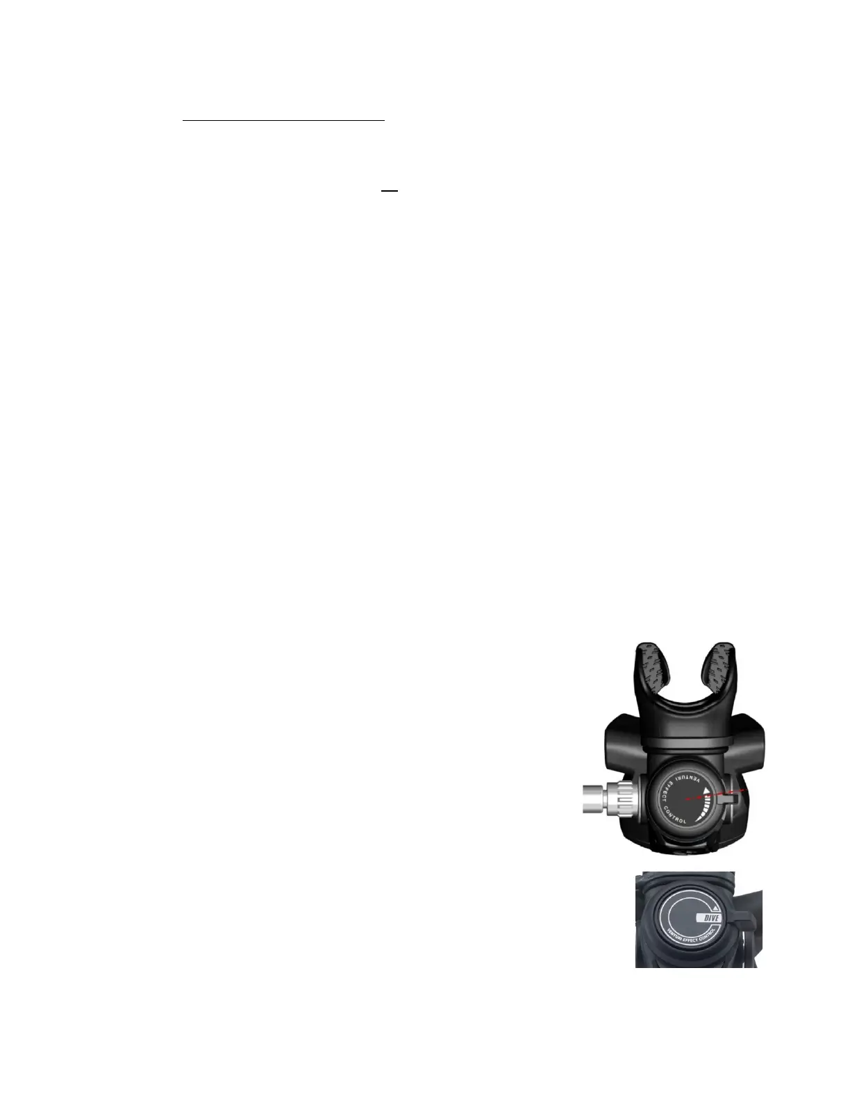
8. Place the dive switch in the Pre-Dive position (forward), and
confirm that freeflow cannot be initiated with a brisk tap on the
purge valve. If freeflow occurs in the Pre-Dive position, confirm
that
a) the mouthpiece is in place,
b) the supplied Intermediate Pressure is 125-145 psi,
c) that cracking effort is at least 1.2”WC, and
d) that the flow vane subassembly has been correctly
assembled and installed.
7. Depressurize the system, and perform a leak test without air supply,
or by closing the inlet with a finger or a plug. Using light suction
applied to the mouthpiece, create a vacuum and assure that there is
no leak into the case. Any leak on suction may require examination
or disassembly to highlight a possible hole in the diaphragm or
exhaust valve, or a malpositioning of the exhaust valve sealing
edge. A cracked case may also be revealed by this test.
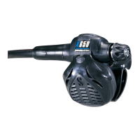
8. Apply the decal (36) to the flow vane cap (35), paying attention to
its orientation. Apply the decal centered in its groove and
positioned as shown in the picture(s) adjacent.
9. Fit the safety pin (48) into the aligned holes of the case (15) and
faceplate (42).
10. Press the decorative cap (11) into the hex recess of the case plug
(10), ensuring that it is secure, and there is no gap between the
plastic trim and the metal plug.
THIS COMPLETES REASSEMBLY AND TUNING
 Loading...