¡GPress this key to enter parameter setting / calibration (when Calibration
Switch is at ON position)
¡GParameter Setup Key (to be used with SET)¡C
¡GCalibration Key (to be used with SET)¡C
¡GNormal Operating/Standby key
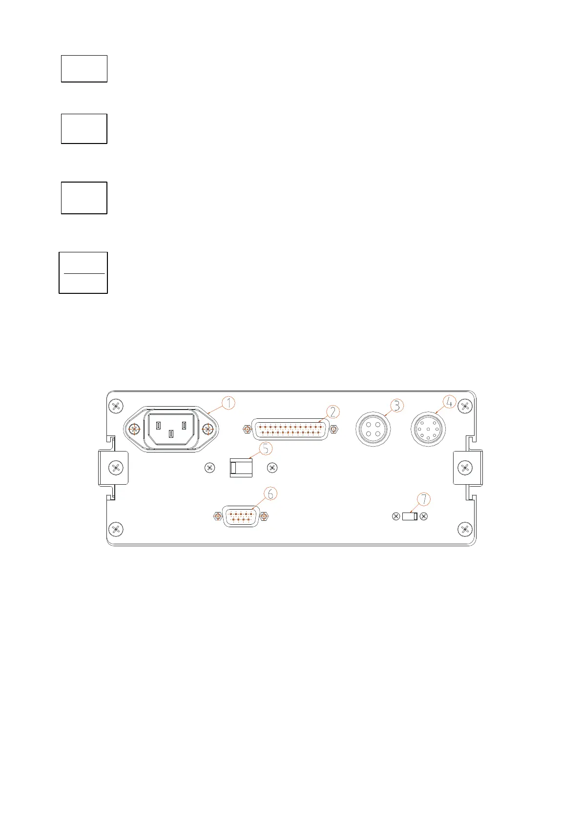
2.2 BACK PANEL LAYOUT AND DESCRIPTION
1. AC Power Socket
2. Printer Interface (D-SUB 25PIN)
3. OP-5L External Display Interface (4PIN)
4. Load Cell Connector (8PIN)
5. Voltage Switch (110V / 220V)
6. RS-232 Interface (D-SUB 9PIN)
7. CAL. SW (when switch to left, function setup and calibration is disabled)
SET
S=
SM
STANDBY
OPERATE