VACON CX Modbus user’s manual Page 20
________________________________________________________________________________________
________________________________________________________________________________________
Vacon Oy Phone +358-201-2121 Fax: +358-201-212 205
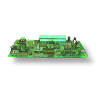
7.4 CONNECTIONS (small Modbus Board for Vacon CXS, Vacon CX211OPT)
7.4.1 Board layout
Terminals:
X5 Screw terminal to Modbus CXS
Diagnostic LED:
H5 Supply Voltage, Red.
H3 led is active if the Fieldbus board has supply voltage.
7.4.2 Modbus connections
Screw Connector connector X5: (Terminal resistors not included in the package)
Signal Connector X5 Description
Shield X5-1 Cable shield
- X5-2 -
RxD/TxD-P X5-3 Receive/Transmission data positive (B)
RxD/TxD-N X5-4 Receive/Transmission data negative (A)
DGND X5-5 Data Ground
Table 7-2. Screw connector terminals
Note! If Vacon is the last device then the bus termination must be set. Install the resistors to the screw terminal
(see table 5-1)
H3
X5
H1
1 2 3 4 5
Figure 7-1. Modbus board
120 Ω
Termination for
the last node
H5

 Loading...