Do you have a question about the VADA FLOW BOSS VFB-DSU and is the answer not in the manual?
Lists technical specifications of the VFB-DSU, including dimensions, voltage, and IP rating.
Provides a recommendation to install a float switch for enhanced pump protection and system performance.
Details the various applications where the Vada Flow Boss Digital Water Switching Unit is suitable for use.
Lists all supplied components and necessary items to be provided by the user for installation.
Guides through the initial preparation steps for the Digital Water Switching Unit itself.
Provides step-by-step instructions on how to connect the switching unit to the water pump.
Offers practical advice for connecting with submersible pumps and using thread tape correctly.
Details the procedure for installing the float switch within the water tank.
Specifies the required pipe marking standards and procedures for connected pipes.
Explains the safe and correct procedures for making the electrical connections to the unit.
Outlines the steps required to commission the Vada Flow Boss unit after installation.
Guides the user through the initial startup process and system checks.
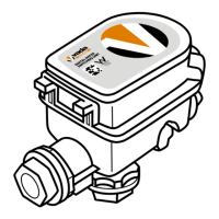
Identifies and explains the function of each button, indicator, and the LCD display on the unit.
Highlights and explains advanced features like historical water consumption tracking.
Details how to access and view monthly historical water usage data saved by the unit.
Explains how to use the 'MODE' button to display real-time flow rate and pressure readings.
Explains how to check the pump's current draw via the unit's display for performance monitoring.
Defines the flow rate setting at which the pump will automatically stop operation.
Sets the maximum duration the pump can run to prevent damage from continuous operation.
Defines the flow rate setting at which the pump will automatically activate.
Sets the minimum pressure threshold required for the pump to operate.
Configuration option to set the unit to operate with or without a float switch.
Provides a guide to navigating and accessing the unit's advanced configuration menu.
Compiles essential technical data including supply voltage, electrical load, and IP rating.
Presents a graph illustrating the pressure loss characteristics for both mains and pump water flow.
Covers common operational scenarios and states like 'Loss of Prime' and 'Loss of Power'.
Explains how to address the pump losing prime and the recommended preventative measures.
Describes how the unit handles situations where the town water supply is unavailable.
Details the system's behavior during power interruptions and upon restoration.
Explains the operational logic and behaviour when the unit is configured without a float switch.
Provides instructions on how to safely disconnect and remove the unit for servicing.
Details the procedure to reset the system after it has entered 'loss of prime' mode.
Error Code 1 indicates the tank is empty and the unit is using mains water.
Error Code 2 signifies that the pump has reached its maximum configured run time.
Error Code 3 flags an over-current condition detected in the pump motor.
Error Code 4 indicates no pump load or a blown fuse, requiring inspection.
Solutions for scenarios where water delivery is absent or pump performance is poor.
Troubleshooting steps for when the unit enters 'loss of prime' state, impacting water supply.
Addresses issues of the pump cycling erratically or running continuously without demand.
Provides guidance to resolve complete loss of water supply from the system.
Solutions for diagnosing and fixing issues related to low water pressure from the pump.
Lists the specific requirements and conditions that must be met for the warranty to be valid.
Details the exclusions from warranty coverage, such as wear and tear or improper use.
Outlines Reece's exclusion of liability for consequential damages and warranties beyond stated terms.