The Vahterus Plate & Shell Heat Exchanger (PSHE) is a robust and versatile device designed for efficient heat transfer in various industrial applications. These heat exchangers are designed and manufactured in compliance with legislation relating to pressure equipment, with design codes typically including ASME VIII Div. 1 and the Pressure Equipment Directive (CE).
Function Description
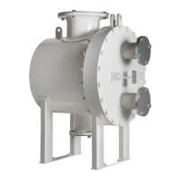
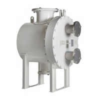
The primary purpose of a Vahterus PSHE is to transfer heat from one fluid to another using a corrugated heat transfer plate. The construction allows for fluids to flow alternately through the plate pack, controlled in either counter-current, co-current, or cross-flow configurations. The Plate & Shell heat exchanger consists of circular plates welded into a pack, which is then mounted in a pressure vessel. The flow on the plate side passes through connections on the end plates via the plate pack, while the flow on the shell side passes through shell connections via the plate pack using a flow director.
Vahterus offers several product types:
- Plate & Shell Fully Welded: Features a welded pack of circular plates inside a welded pressure vessel. This model is suitable for liquid-liquid, condenser, evaporator, and cascade applications and can be single or multi-pass.
- Plate & Shell Openable: A fully welded and removable plate pack inside an openable shell, allowing for easier maintenance and inspection.
- Plate & Shell Compact: All connections are on the end plate, and it can be single or multi-pass.
- Plate & Shell VES: A heat exchanger with an external droplet separator.
- Plate & Shell Combined: A heat exchanger with a combined droplet separator.
- Plate & Shell EGE: An exhaust gas economiser.
Important Technical Specifications
The general range of parameters for Vahterus PSHEs includes:
- Volume: From 0.0002 m³ to 5 m³.
- Temperature: From -196°C to +600°C.
- Pressure: Standard range of 10/16/25/40/60 bar(g), with up to 170 bar(g) available on request.
- Materials: Common materials include Carbon Steel (P235GH, P265GH, P355NL2, SA516Gr70, SA333 etc.), AISI 316/316L, 1.4404/304L, 1.4403, and Titanium Gr. 1. Other materials like Hastelloy (C22 & C276), Nickel 201, SMO 254 (EN 1.4547), AISI 904 (EN 1.4539), and Duplex (EN 1.4462) are available on request.
- Working Mediums: Suitable for liquids of all groups, gases of all groups, superheated and saturated steam of all groups, and two-phase mediums (liquid-gaseous mixtures) of all groups. It can handle various refrigerants from group 1 (R170, R1150, R290, R717, R1270) and group 2 (R134a, R744, R404a, R410a, R407F, R507a, and all other refrigerants from group 2).
- Corrosion Allowance: For carbon steel, it is at least 1 mm. Greater allowances must be specified when ordering.
- Fatigue: 500 full pressure cycles are allowed without separate calculations. If this number is exceeded, the heat exchanger should be tested (pressure test and possible NDE tests) with reference to local laws.
Usage Features
- Installation: Adequate space should be provided around the heat exchanger for mounting, insulation, and maintenance. For openable models, space equal to the total length at the front is needed to remove the plate pack. Lifting is typically done using welded lifting lugs or eye lugs; if not provided, a textile belt around the shell should be used. Mounting brackets are designed only to bear the weight of the heat exchanger and not external forces like piping stress, wind load, or earthquakes.
- Piping: All piping connected to the exchanger must be flushed before connection. Connections are marked and should follow the GA drawing. The piping system must be flexible to prevent thermal expansion from overloading nozzles or causing vibration. All pipe connections must have shut-off valves, with slow valve action recommended for gradual flow rate changes during start-up/shut-down. Filters are recommended if process fluids contain solids. A relief valve is essential to prevent excess design pressure. For multiple units in parallel, flow distribution should be even.
- Steam Applications (Condensers): Pipelines should follow best steam flow manufacturing practices. Units are placed horizontally to prevent condensate accumulation. Steam traps (drains) and droplet separators are recommended before and after the heat exchanger. A striker plate is provided on the shell side for water vapor to prevent water hammer. Condensate side control requires the condensation temperature on the hot side to be no higher than the evaporating temperature on the cold side.
- Insulation: Recommended if shell side temperature is below -10°C or above 65°C to prevent burns or frostbite.
- Pressure Testing: All PSHE units undergo pressure tests: plate packs are leak-tested pneumatically under water, and the whole unit undergoes a hydraulic pressure test. Test pressures are specified on the Technical Data sheet and nameplate. Pressure should be increased slowly to prevent shocks.
- Start-up: Before start-up, check that pipe connections are secured, drain valves are closed, the heat exchanger and pipelines are vented, and safety appliances are connected. Gradually increase flow on the cold side first, then the hot side. The general heating rate is max. 5°C/minute.
- Shut-down: Gradually decrease flow on the hot side until it stops completely, then close the cold side. Close inlet and outlet valves, and drain and vent the heat exchanger.
Maintenance Features
- Cleaning: The unit's performance should be monitored by measuring temperature and pressure loss. Cleaning is required if losses exceed permitted levels.
- Backwards Flow Cleaning: Involves reversing water flow or using a cleaning medium. Close valves 1.1 and 1.2 (temperature must be between 10°C and 30°C), drain liquid from the side to be cleaned, connect a hose to valve 2.1, and flow water for 10-15 minutes. Check for organic compounds and dirt removal. Stop water flow, close valve 2.1. Fill the heat exchanger with liquid from the start-up procedure, detailed above. Close valve 2.2. If the surface remains dirty, a specific detergent should be used.
- Chemical Cleaning: A chemical cleaning company should be consulted. The cleaning process should involve common cleaning agents, with non-harmful additives. The cleaning agent should be chosen based on the dirt and impurities. After chemical treatment, plates must be rinsed with clean water.
- Mechanical Cleaning (Openable Models): The plate pack can be removed from the shell and cleaned using a high-pressure cleaner. This allows for visual inspection of heat transfer surfaces.
- Periodical Inspections:
- Fully Welded Heat Exchangers: Internal inspection of the shell chamber with an endoscope after 5 years, and a pressure test after 10 years.
- Openable Heat Exchangers: Internal inspection of the shell chamber with an endoscope after 5 years, and a pressure test, internal inspection by opening the unit, and visual check of the shell chamber and plate pack after 10 years. Local requirements for pressure vessel inspections must be followed.
- Troubleshooting: The manual provides a detailed troubleshooting guide for common issues like poor performance, pressure difference, external/internal leakage, pressure shock, mechanical wear, and gradual decline in heat transfer performance, with recommended checks and actions.
- Spare Parts/Special Tools: Flow directors, plate packs, gaskets, and guide bars are available as spare parts, supplied with the exchanger serial number.
- Packing and Storage: Equipment is checked and packed in sturdy wooden boxes made from Finnish pine, harvested sustainably. The packaging materials are recyclable. Heat exchangers should be stored indoors in a dry, dust-free location, with temperatures from +1°C to +40°C and relative humidity up to 90%. Maximum storage period is 12 months. Long-term storage (5 years) is possible if the equipment is ordered with nitrogen filling.