Boiler Installation Sequence 5
Instructions for Installation and Servicing turboMAX plus and thermoCOMPACT R1 21
Abb. 0.0 Bildunterschrift
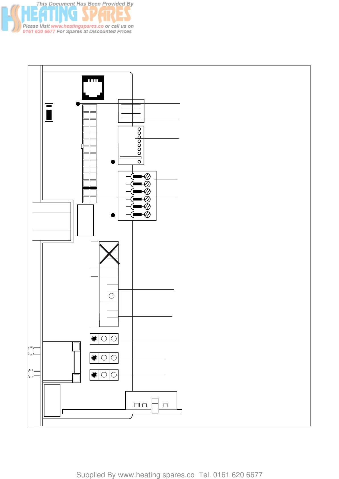
Fig. 5.13: Connection wiring
5.16 Electronic board layout
Socket X2 for internal unit components
Socket X4 for diverter valve
Socket X7 for accessory box connection
Socket X8 for VRC-VC connection
Room thermostat, 230 V: connections 3, 4 and 5
Mains power supply: connections L, N and earth
Socket X12: pump connection
Socket X14: gas valve connection
Socket X13: fan connection
Do not use!
Socket for fan control cable (637 and 837 only)