Troubleshooting 5
0020160592_00 auroFLOW plus Instructions for use 9
5 Troubleshooting
5.1 Reading fault messages
Fault messages have priority over all other displays. If a fault
occurs in the solar system, the solar system switches itself
off. The display of the solar charger displays a fault code in
place of the basic display. A plain text display explains the
displayed fault code.
If multiple faults occur at the same time, the display shows
the corresponding fault codes for two seconds each in se-
quence.
▶ If the solar charger displays a fault message, contact
your approved competent person.
Note
Status messages about the condition of the
solar system can be called up using the Live
Monitor (→ Page 12) function.
5.1.1 Fault message
Fault messages appear on the display approx. 20 seconds
after a fault has occurred. If a fault is present for at least
three minutes, a fault message is recorded in the fault
memory of the solar control.
Note
Only a competent person can eliminate the cause
of the faults described below and delete the fault
memory.
Fault code Fault text
20 Shut-down of temperature limiter
1272 Electronics fault in cylinder charge pump
1273 Electronics fault in solar pump
1274 Electronics fault in solar pump 2
1275 Cylinder charge pump blocked
1276 Solar pump blocked
1277 Solar pump 2 blocked
1278 T5 collector sensor fault
1279 T6 cylinder temperature sensor fault
1281 T1 temperature sensor fault
1282 T2 temperature sensor fault
1283 T3 temperature sensor fault
1284 T4 temperature sensor fault
1355 Volume flow sensor cylinder circuit fault
6 Auxiliary functions
The digital information and analysis system provides auxili-
ary functions via the menu.
6.1 Operation in the menu
Press and ("i") at the same time to access the menu.
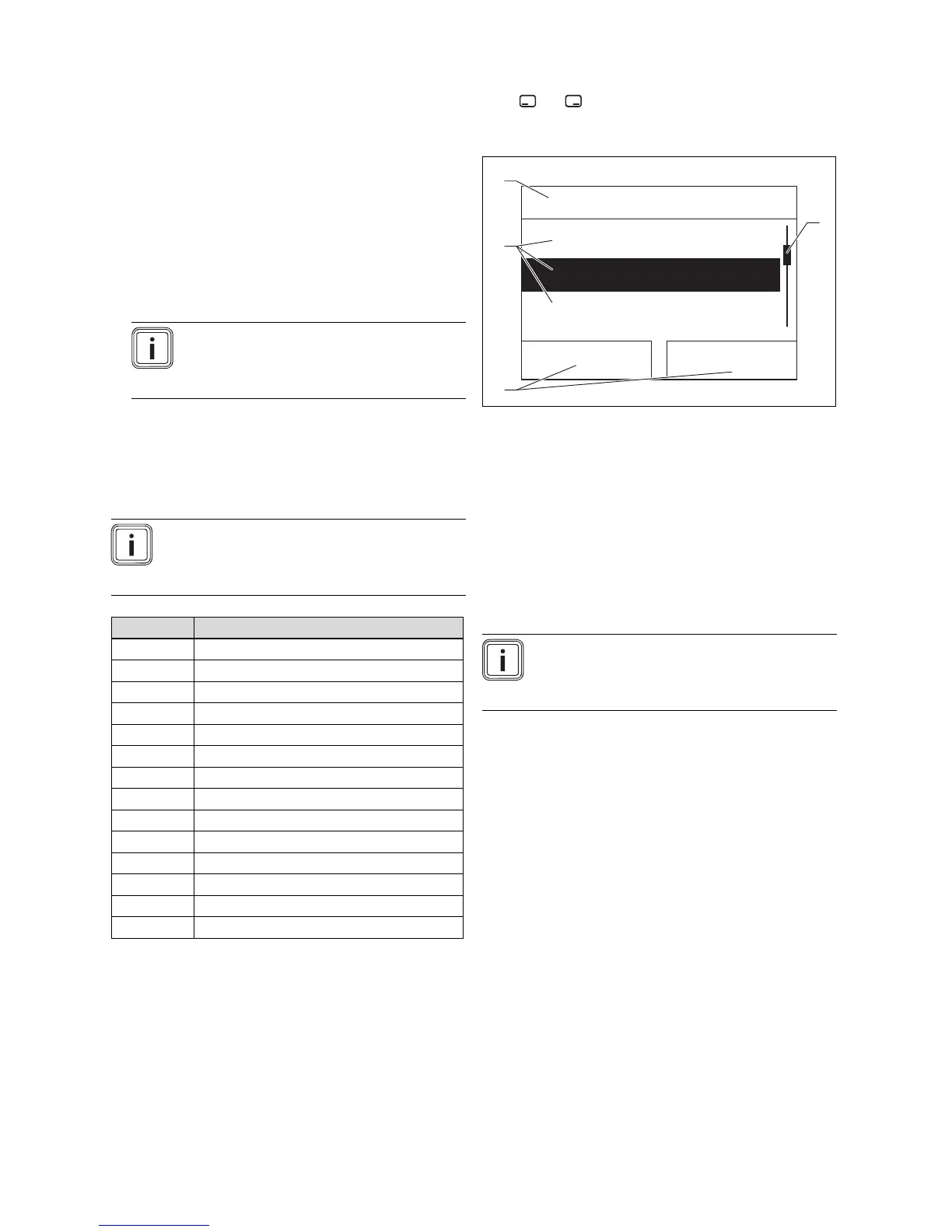
6.1.1 Design of the menu
Menu
Live Monitor
Information
Basic settings
SelectBack
1
4
2
3
1 Scroll bar
(only appears if there are
more list entries than can
be shown at once on the
display)
2 Current functions of the
right and left selection
buttons
(Soft key functions)
3 Selection level list entries
4 Name of the selection
level
The Digital Information and Analysis System has a menu
containing up to two selection levels (sub-menus).
The selection levels are used to navigate to the setting level
required to read or change settings.
Note
Path details at the start of an instruction specify
how this function can be accessed, e.g. Menu →
Information → Contact data.