14 Installation and maintenance instructions ecoFIT pure 0020230535_07
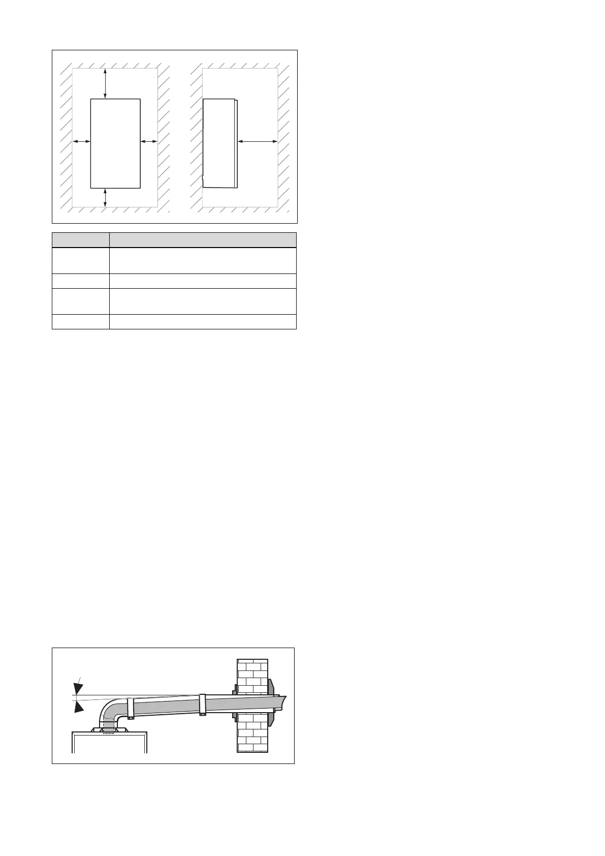
6.4 Minimum clearances
Minimum clearance
A 150 mm (top air/flue connection)
75 mm (rear air/flue connection)
B 150 mm
C 5 mm
(70 mm, if the side sections have to be removed)
D 500 mm
The boiler and flue are suitable for installation onto and
through combustible materials provided that:
1. Minimum 5 mm clearance is maintained around the
circumference of the flue (air intake).
2. The combustible surface and fixings are suitable for
supporting the load.
3. The minimum clearances from the boiler case are main-
tained.
6.4.1 Compartment Ventilation
The boilers are very high efficiency appliances.
As a consequence the heat loss from the appliance casing
during operation is very low.
Compartment ventilation is not required as the products are
only certified, and can only be fitted with a concentric flue
system.
6.5 Air/flue pipe
6.5.1 Regulation
Different flue outlet configurations can be carried out.
– Consult the installation manual for air/flue gas systems
for more information about the other possibilities and
associated accessories.
– Standard flue terminal kits have an in-built fall back to
the boiler to drain the condensate. These can be fitted
level between the appliance and the termination position.
All other extended flues must have a fall of at least 44
mm/m.
The maximum length of the flue outlet is defined according to
its type (for example C13).
– Whatever the kind of flue system chosen, observe the
minimum distances to position the flue terminals.
– To install the flue, refer to the separate flue instruction
supplied with your appliance.
– Explain these requirements to the user of the appliance.
In GB the minimum acceptable siting dimensions for the
terminal from obstructions, other terminals and ventilation
openings are shown in diagram overleaf.
In IE the minimum distances for flue terminal positioning
must be those detailed in I.S. 813 “Domestic Gas Installa-
tions”.
The terminal must be exposed to the external air, allowing
free passage of air across it at all times.
Being a condensing boiler some pluming may occur from
the flue outlet. This should be taken into consideration when
selecting the position for the terminal.