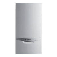
Do you have a question about the Vaillant ecoTEC plus 806 VU GB 806/5-5 and is the answer not in the manual?
| ErP efficiency class | A |
|---|---|
| NOx class | 5 |
| Maximum operating pressure | 3 bar |
| Electrical protection | IPX4D |
| Fuel | Natural Gas |
| Max. Working Pressure | 3 bar |
| Electrical supply | 230 V / 50 Hz |
Classifies warnings by severity using symbols and signal words.
Defines the product's purpose and conditions for safe operation.
Covers risks from inadequate qualifications, flue gas, electric shock, burns, etc.
Work must only be done by qualified persons.
Escaping flue gas can cause poisoning.
Danger from hot flue gases if air/flue pipe is not fully installed.
Prohibits storage of flammable materials in the installation room.
Improper operation can cause danger and material damage.
Steps to take if gas is smelled in the building.
Importance of installing necessary safety devices.
Requires at least two people for transport.
Precautions for working on product with live components.
Wait for components to cool before working on them.
Risk from escaping flue gas if condensate siphon is empty.
Risk of scalding from hot water draw-off points.
Use correct tools for screw connections.
Do not install in rooms prone to frost.
Avoid corrosive substances in combustion air.
Observe national regulations, standards, guidelines and laws.
Must observe all operating and installation instructions for system components.
Pass instructions and documents to the system operator.
Specifies which products these instructions apply to.
Explains the Benchmark Scheme responsibilities for manufacturers and installers.
Details the functional elements and layout of the product.
Illustrates and labels the functional components of a specific model.
Illustrates and labels functional components for other models.
Explains the data found on the product's identification plate.
Indicates compliance with basic requirements of applicable directives.
Steps for safely removing the product from its packaging.
Procedure to verify all parts are present and undamaged.
Lists all items included in the product package.
Provides detailed physical measurements and connection points for installation.
Specifies required space around the unit for safe operation and maintenance.
Details clearance requirements from materials that can burn.
Instructions on how to use the provided template for marking installation points.
Guidance on securely attaching the unit to a wall, considering load capacity.
Procedures for safely removing and refitting the front panel.
Step-by-step guide to detach the front casing.
Step-by-step guide to reattach the front casing.
Procedures for safely removing and refitting the top cover.
Step-by-step guide to detach the upper casing.
Step-by-step guide to reattach the upper casing.
Instructions for removing and refitting side panels if necessary.
Steps to detach a side panel.
Steps to refit a side panel.
Procedures and precautions for connecting the gas supply.
Detailed steps for safe and correct gas connection.
Guidance for connecting the water and heating circuits.
Steps for connecting the primary heating pipes.
How to install an expansion vessel for system pressure regulation.
General guidance on connecting hydraulic components.
Steps for correctly installing the condensate collection system.
Instructions for routing the condensate drainage.
How to connect the safety valve for overpressure release.
Procedures for installing the air/flue gas system.
Information on compatible air/flue pipe types and regulations.
Steps for correctly installing the air/flue pipe.
Guidance on connecting the unit to the electrical supply.
How to access and secure the electronic control components.
Steps to safely open the electronics housing.
Steps to safely close the electronics housing.
Connecting the unit to the mains power supply.
Instructions for correctly connecting internal and external wiring.
How to connect external pump groups to the unit.
Guidance on installing an external control unit.
How to integrate external controllers with the unit's electronics.
Instructions for connecting extra components like pumps or valves.
Guide for actuating components using the VR 40 module.
Details on activating flue non-return flaps for cascade operation.
How to connect and control the circulation pump.
Explanation of how the unit's controls and display function.
Procedure to access advanced installer settings and diagnostics.
How to view current operating status codes on the display.
Accessing diagnostic and functional test programs.
Lists required test and measuring equipment for initial start-up.
Procedure for initial start-up by a qualified technician.
Guidance on checking and treating water quality for system integrity.
Instructions for powering up the unit.
Guidance on using the automated setup assistant.
Setting the display language for the unit.
Information on the automatic filling mode during start-up.
Steps for purging air from the heating circuit.
Setting desired temperatures for heating and hot water.
Configuration of the unit's heating output.
Adjusting settings for connected additional components.
Storing contact information for the installer or service technician.
Procedure for completing and exiting the setup assistant.
How to re-access the installation assistant after initial setup.
Accessing configuration and diagnostic menus for system checks.
Utilizing pre-programmed checks for functions and diagnostics.
How to check the system's water pressure.
Measures to avoid damage from insufficient system water pressure.
Detailed steps for filling and removing air from the heating system.
Procedure for flushing the system with cold water before initial operation.
Ensuring the condensate trap is filled with water to prevent gas escape.
Procedure for checking and setting the correct gas-air mixture.
Verifying the initial gas ratio setting for compatibility.
Ensuring the flue gas system is sealed and checking for recirculation.
Procedure for measuring and verifying the gas flow rate.
Verifying the gas inlet working pressure at the reference test point.
Measuring and adjusting CO2 levels for optimal combustion.
Verifying gas, heating, and hot water circuits for leaks.
Confirming the unit operates correctly in heating mode.
Confirming correct operation of hot water production.
Procedure for flushing the system with hot water after initial operation.
How to access and navigate diagnostic codes for system adaptation.
Adjusting the maximum heating output for optimal performance.
Configuring pump run-on times and operating modes (Eco/Comfort).
Setting the upper limit for the heating water temperature.
Option to control heating based on return flow temperature.
Importance of regular checks and scheduled maintenance for safety and longevity.
Guidance on using original manufacturer spare parts for reliable operation.
How to use the function menu to test individual components.
Procedure for running self-tests on the unit's electronic components.
Steps for safely removing the gas-air mixture assembly.
Instructions for cleaning the primary heat exchanger.
Inspecting the burner for damage and wear.
Guide for replacing ignition and ionisation components.
Procedure for cleaning and refilling the condensate trap.
Steps for refitting the gas-air mixture assembly after maintenance.
Information to provide when contacting a service technician.
How to check for and interpret service messages.
How to identify and understand error codes displayed by the unit.
Accessing the history of past faults to aid diagnosis.
Procedure to clear the stored fault codes.
Using diagnostic functions to test product components.
Utilizing pre-programmed checks for troubleshooting.
Restoring all settings to their default values.
Steps to safely prepare the unit before commencing repairs.
Procedure for emptying the unit of water for maintenance.
Final checks after completing maintenance tasks.
Detailed guides for replacing various internal parts.
Step-by-step instructions for replacing the gas valve.
Instructions for removing and installing the burner assembly.
How to replace the insulating mat on the burner door.
Guide for replacing the unit's fan.
Instructions for removing and installing the heat exchanger.
Procedures for replacing electronic control boards and displays.
Steps for safely shutting down and disconnecting the unit.
Instructions for correctly disposing of product packaging.
A comprehensive checklist for the initial installation and commissioning process.
Guidelines for flue terminal placement relative to openings and building features.
Regulatory text regarding fan-supported flue gas system terminal positioning.
Specific considerations for flue pipe openings near eaves and balconies.


 Loading...