Installation and maintenance instructions ecoTEC 0020029173_018
G
N
N
MM
A
I
I
O
H
H
C
B
L
J
Q
Q
Q
K
P
D, E
F
I
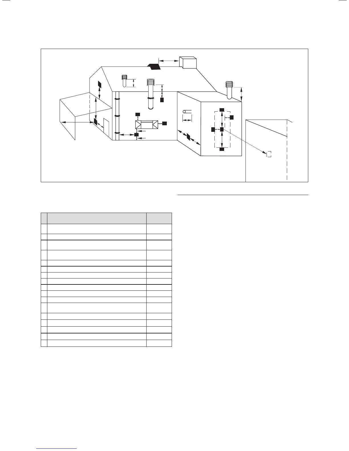
Fig. 3.3 Termination of the flue pipe
The flue assembly shall be so placed or shielded as to
prevent ignition or damage to any part of the building.
Location
Minimum
dimensions
A
Directly below an opening, air brick, opening win-
dows, etc.
300 mm
B Above an opening, air brick, opening window, etc. 300 mm
C
Horizontally to an opening, air brick, opening
window, etc.
300 mm
D
Below temperature-sensitive building compo-
nents e.g. plastic gutters, soil pipes or drain pipes
75 mm
E Below eaves 200 mm
F Below balconies or car port roof 200 mm
G From a vertical drain pipe or soil pipe 150 mm
H From an internal or external corner 200 mm
I Above ground, roof or balcony level 300 mm
J From a surface facing the terminal 600 mm
K From a terminal facing the terminal 1200 mm
L
From an opening in the car port (e.g. door, win-
dow) into the dwelling
1200 mm
M Vertically from a terminal on the same wall 1500 mm
N Horizontally from a terminal on the same wall 300 mm
O From the wall on which the terminal is mounted N/A
P From a vertical structure on the roof N/A
Q Above intersection with roof 300 mm
Table 3.1 Position of the termination in a fan-assisted
concentric flue pipe
h
Note!
In addition, the terminal should not be nearer
than 300 mm to an opening in the building
fabric formed for the purpose of
accommodating a built–in element such as a
window.
BS 5440–1 It is recommended that the fanned flue
terminal should be positioned as follows:
a) at least 2 m from an opening in the building directly
opposite, and
b) so that the products of combustion are not straightly
directed to discharge across a boundary.
1) Dimensions D, E and F:
These clearances may be reduced to 25 mm without
affecting the performance of the boiler. In order to
ensure that the condensate plume does not affect
adjacent surfaces the terminal should be extended as
shown in fig. 3.3.
2) Dimension H:
This clearance may be reduced to 25 mm without
affecting the performance of the boiler. However, in
order to ensure that the condensate plume does not
affect adjacent surfaces a clearance of 300 mm is
preferred. For IE, recommendations are given in the
current edition of IS 813.
3 Safety instructions and regulations

 Loading...


