Appendix
0020234040_02 eloSTOR exclusive Installation and maintenance instructions 15
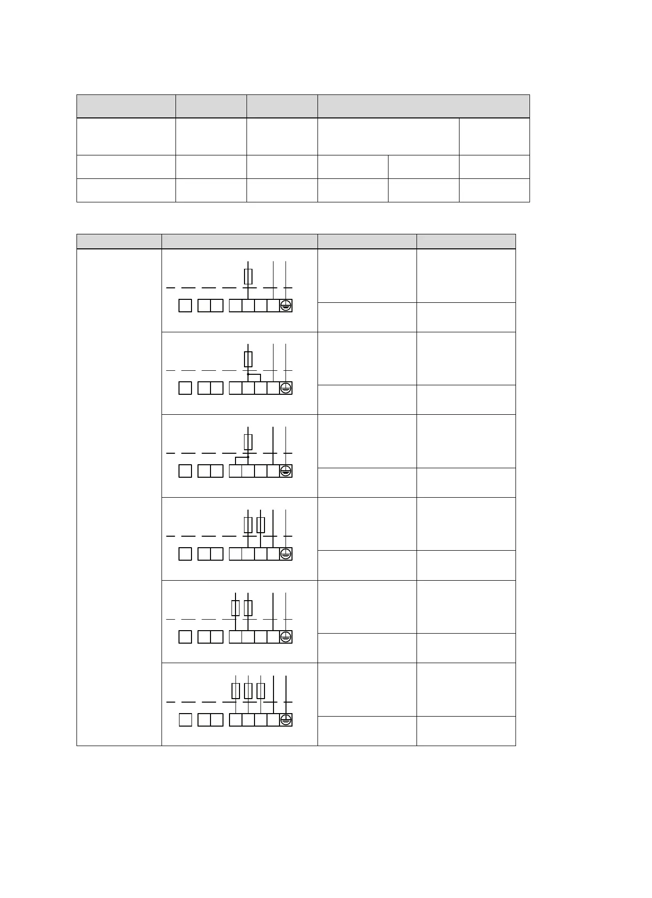
D.2 Overview of the configuration types
On-demand
switching (Co0)
Single circuit
switching (Co1)
Twin circuit switching (Co2)
Available operating
mode
Scald protection
Manual
Scald protection
Manual
Smart
Scald protection
Manual
Smart
EVU contact Not working Not working Open: High tariff Closed: Low
tariff
Not working
Heating elements actu-
ated by
Sluice Sluice Sluice Smart Control
module
Sluice
D.3 Selecting the power
Configuration type Mains connection Basic load Rapid heating
Single-circuit switch-
ing
On-demand switch-
ing
– VEH 50/8-7
– VEH 80/8-7
– VEH 100/8-7
2 kW
–
– VEH 120/8-7
1.5 kW
–
– VEH 50/8-7
– VEH 80/8-7
– VEH 100/8-7
4 kW
–
– VEH 120/8-7
3 kW
–
– VEH 50/8-7
– VEH 80/8-7
– VEH 100/8-7
4 kW
–
– VEH 120/8-7
4.5 kW
–
– VEH 50/8-7
– VEH 80/8-7
– VEH 100/8-7
4 kW
–
– VEH 120/8-7
3 kW
–
– VEH 50/8-7
– VEH 80/8-7
– VEH 100/8-7
4 kW
–
– VEH 120/8-7
4.5 kW
–
– VEH 50/8-7
– VEH 80/8-7
– VEH 100/8-7
6 kW
–
– VEH 120/8-7
6 kW
–
By bridging terminal 4/5, heating elements 1 and 4 can be interconnected in the low tariff. The heating elements' outputs are
listed in the following table. Find out from your energy supply company what the maximum power consumption is for low-tariff
switching.
 Loading...