14
INSTALLATION OF THE HORIZONTAL AIR/FLUE DUCT (REAR OUTLET)
(TURBOMAX AND THERMOCOMPACT ONLY)
Rear outlet flue accessory
Accy No: 303 817
Contents of the accessory
• Rear air/flue duct
• Flue securing collar Ø 100
including fixing screws and wall
plugs
• Air duct connection piece and
screws
• Flue cap
• Rubber bung
• Air pressure tube extension and
connecting nipple
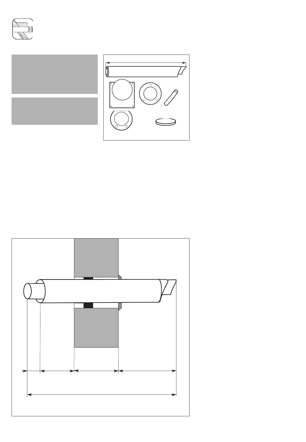
Fig. 3.1: Horizontal wall duct
LAS Euro B/S 073/1GB
IMPORTANT:
The flue hole should be cut with a
slight fall to outside of 1° to prevent
rain water entering the flue.
Minimum top clearance for rear
installation is 100 mm.
IMPORTANT:
To install this accessory access must
be available to the proposed flue exit
point outside the dwelling.
Preparation
• Determine the installation site for
the boiler with reference to the
installation and servicing
instructions supplied with the
boiler.
• Ensure that all installation and
service clearances are available
and that the boiler flue can be
installed as detailed in these
instructions.
• Fix the paper template, supplied
with the boiler, to the wall
ensuring that the centreline of the
template is vertical using a
plumbline or spirit level.
• The installation template details
the position of the flue exit hole
for rear outlet installations.
Ensure that the correct flue exit
hole has been identified.
• Once the position of the flue exit
hole has been determined, the
hole should be cut through the
wall using a core drill of 107 mm
diameter.
• Measure the thickness of the wall
through which the flue will pass.
This is dimension C.
• (Note: If using the top connection
spacer frame accessory make an
additional 45 mm allowance for
the depth of the frame).
• Cut the air duct and flue duct to
the lengths shown in figure 3.2.
• When cutting the air and flue
ducts it is important to remove any
burrs with a file, this ensures easy
fitting of the ducts.
 Loading...