PART 1 CONCENTRIC 60/100
PLANNING THE AIR/FLUE DUCT LAYOUT
9
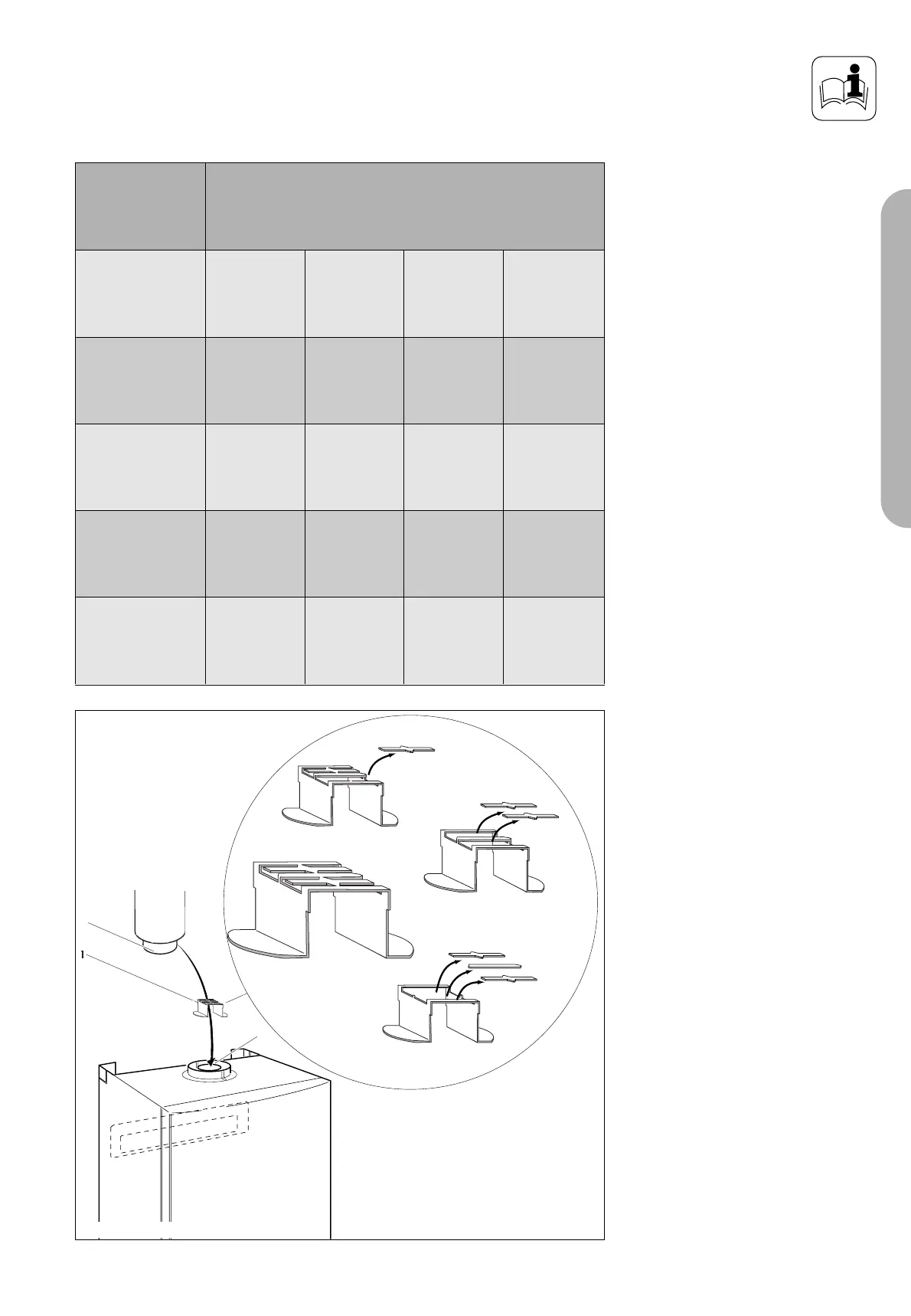
Fig. 1.11: Flue restrictor rings
Flue restrictor rings
The flue restrictor ring marked A, C
or D is packed with the boiler
connection accessories. The restrictor
ring should be fitted as shown in the
diagram according to the equivalent
flue length in the table.
The total equivalent flue length is the
total length of the flue (including the
terminal assembly for vertical flues),
plus the resistance of any bends or
elbows used.
- equivalent length of 90° elbow is
1 m
- equivalent length of 45° elbow is
0.5 m
• Push the restrictor (1) into the flue
connection of the appliance (3)
• Connect the flue/elbow (2) into
the flue connection of the
appliance (3).
Note:
thermoCOMPACT 615 boilers do not
require a seperate restrictor ring and
are supplied without the restrictor.
The required restriction is designed
into the flue connection piece for
these boilers.
thermoCOMPACT
615/2 E
thermoCOMPACT
620/2 E
thermoCOMPACT
624/2 E
turboMAX plus
824/2 E
turboMAX
pro 24/2 E
thermoCOMPACT
628/2 E
turboMAX plus
828/2 E
turboMAX pro
28/2 E
Use restrictor A
---
Use restrictor D
---
No flue restrictor
---
< 6.3 m
---
---
---
---
---
---
< 2.3 m
> 2.3 m
Use restrictor C
--- --- < 5.5 m ---
Total equivalent flue length
(incl. terminal any bends / elbows used)
 Loading...