5Operating and installation manual for VR 61 mixer module
4 Incorporation of the VR 61 in
the heating system
The application possibilities of the mixer module VR 61
are shown in the four hydraulic diagrams.
In each case these are maximum configurations.
Some of the components can be optional.
Hydraulic drawing 1
– an uncontrolled heating circuit
– a controlled heating circuit (controlled 3 way valve)
– circulation pump for hot water controlled by VR 61
– hot water via VUV (priority changeover valve)
Hydraulic drawing 2
– an uncontrolled heating circuit
– a controlled heating circuit (controlled 3 way valve)
– circulation pump for hot water controlled by VR 40
– charging pump for storage tank controlled by VR 61
Hydraulic drawing 3
– an uncontrolled heating circuit
– a controlled heating circuit (controlled 3 way valve)
– circulation pump for hot water controlled by VR 61
– charging pump for storage tank controlled by heating
equipment
Hydraulic drawing 4
– two uncontrolled heating circuits (controlled by motor
valves)
– heating pump integrated in the heating equipment
– circulation pump for hot water controlled by VR 40
– hot water controlled by motor valve via VR 61
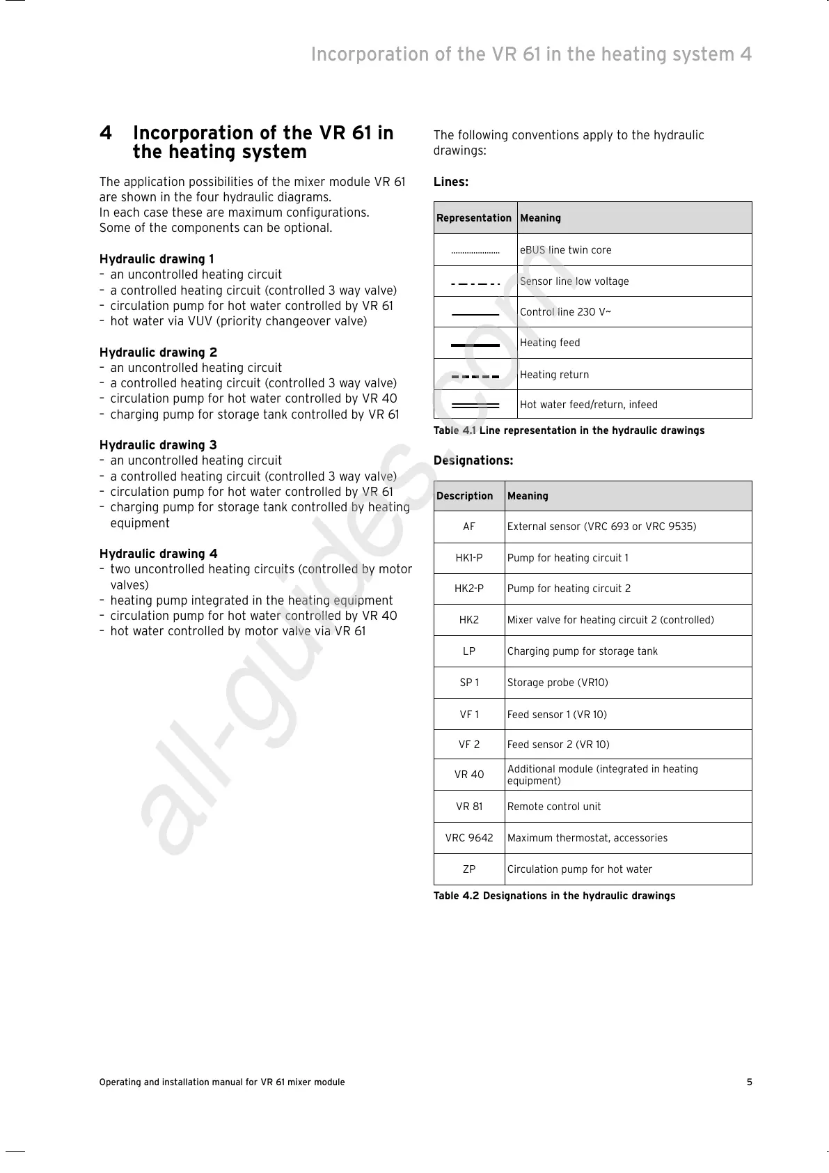
The following conventions apply to the hydraulic
drawings:
Lines:
Representation Meaning
eBUS line twin core
Sensor line low voltage
Control line 230 V~
Heating feed
Heating return
Hot water feed/return, infeed
Table 4.1 Line representation in the hydraulic drawings
Designations:
Description Meaning
AF External sensor (VRC 693 or VRC 9535)
HK1-P Pump for heating circuit 1
HK2-P Pump for heating circuit 2
HK2 Mixer valve for heating circuit 2 (controlled)
LP Charging pump for storage tank
SP 1 Storage probe (VR10)
VF 1 Feed sensor 1 (VR 10)
VF 2 Feed sensor 2 (VR 10)
VR 40
Additional module (integrated in heating
equipment)
VR 81 Remote control unit
VRC 9642 Maximum thermostat, accessories
ZP Circulation pump for hot water
Table 4.2 Designations in the hydraulic drawings
Incorporation of the VR 61 in the heating system 4
 Loading...