7Operating and installation manual for VR 61 mixer module
4.2 Hydraulic drawing 2
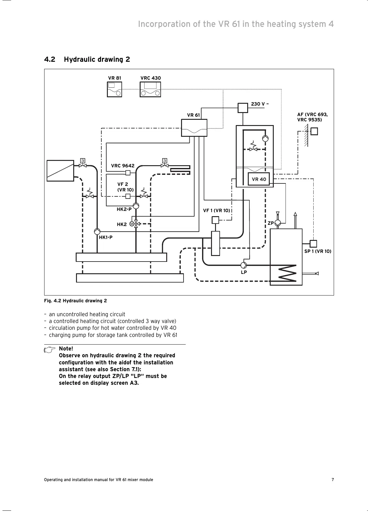
Fig. 4.2 Hydraulic drawing 2
– an uncontrolled heating circuit
– a controlled heating circuit (controlled 3 way valve)
– circulation pump for hot water controlled by VR 40
– charging pump for storage tank controlled by VR 61
h
Note!
Observe on hydraulic drawing 2 the required
configuration with the aidof the installation
assistant (see also Section 7.1):
On the relay output ZP/LP "LP“ must be
selected on display screen A3.
Incorporation of the VR 61 in the heating system 4
VR 61
VRC 430VR 81
AF (VRC 693,
VRC 9535)
VF 1 (VR 10)
SP 1 (VR 10)
VF 2
(VR 10)
VRC 9642
HK1-P
HK2-P
HK2
230 V ~
ZP
LP
VR 40

 Loading...