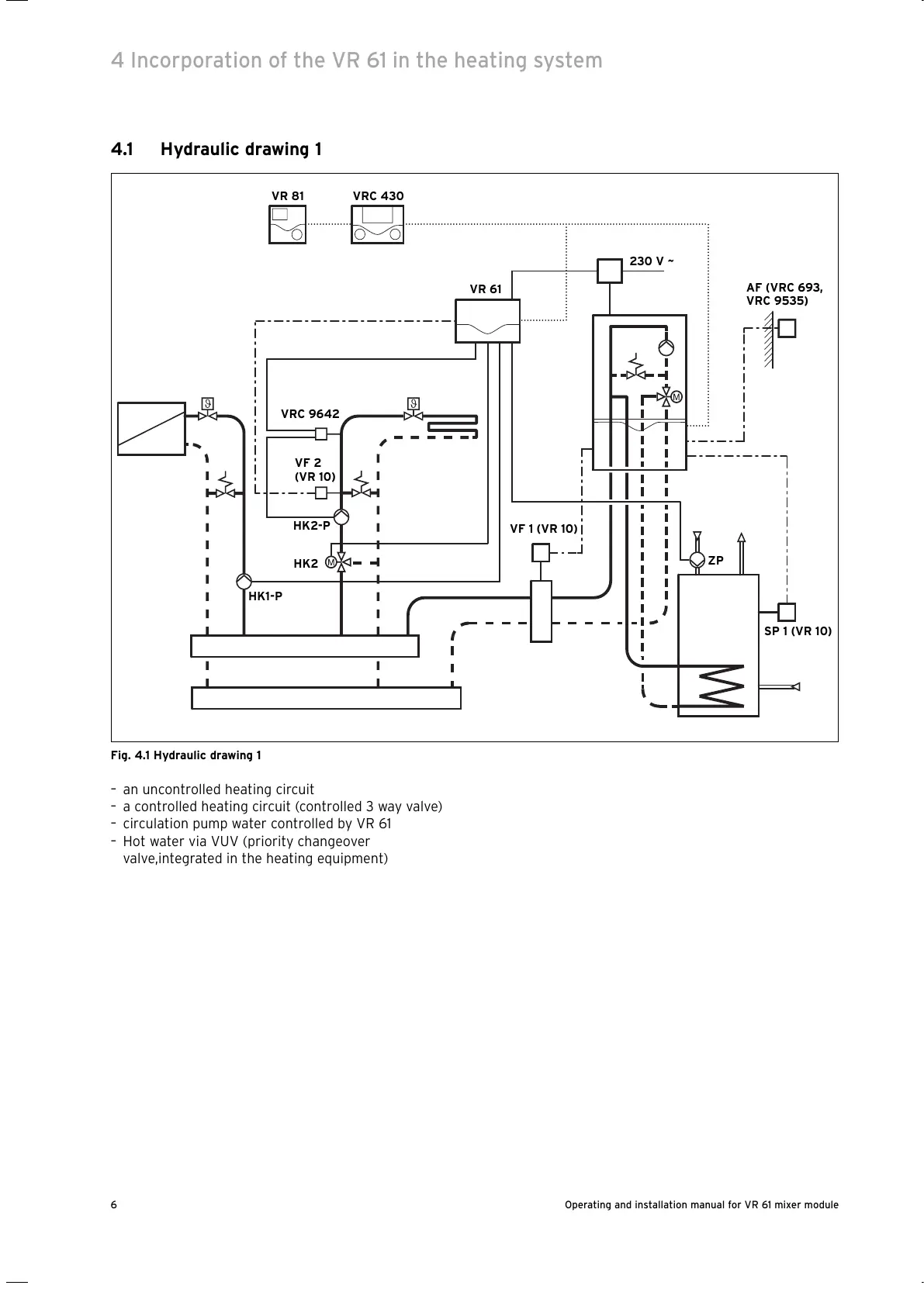
4.1 Hydraulic drawing 1
Fig. 4.1 Hydraulic drawing 1
– an uncontrolled heating circuit
– a controlled heating circuit (controlled 3 way valve)
– circulation pump water controlled by VR 61
– Hot water via VUV (priority changeover
valve,integrated in the heating equipment)
4 Incorporation of the VR 61 in the heating system
Operating and installation manual for VR 61 mixer module6
VR 61
VRC 430VR 81
AF (VRC 693,
VRC 9535)
VF 1 (VR 10)
SP 1 (VR 10)
VF 2
(VR 10)
VRC 9642
HK1-P
HK2-P
HK2
230 V ~
ZP