2 Notes on the documentation
4
2 Notes on the documentation
2.1 Observing other applicable documents
▶ You must observe all operating instructions enclosed with
the system components.
2.2 Storing documents
▶ Keep this manual and all other applicable documents
safe for future use.
2.3 Applicability of the instructions
These instructions apply only to:
VRC 700 – Article number
Great Britain
0020171316
3 Product overview
3.1 CE label
The CE label shows that the products comply with the basic
requirements of the applicable directives as stated on the
identification plate.
The declaration of conformity can be viewed at the manufac-
turer's site.
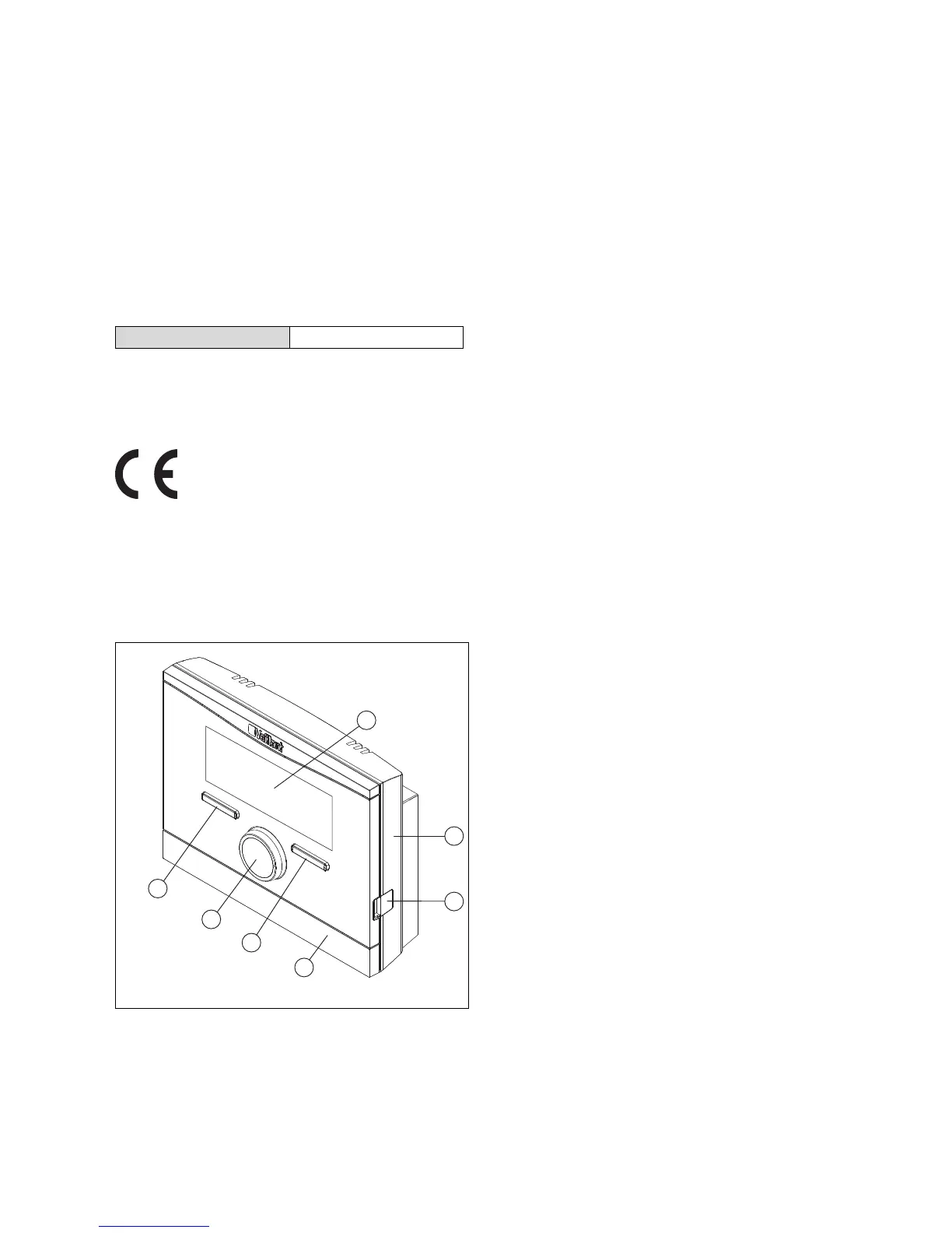
3.2 Design of the product
1 Display
2 Wall-mounting base
3 Diagnostics socket
4 Wall-mounting base
cover
5 Selection button
6 Rotary knob
3.3 Identification plate
The identification plate is located inside the product and is
not accessible from the outside.
3.4 Serial number
The 10-digit article number can be found in the serial num-
ber. You can view the serial number under Menu → Inform-
ation Serial number. The article number is found in the
second line of the serial number.
3.5 Control function
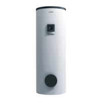
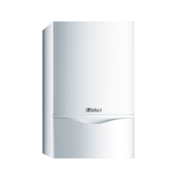
The product controls the Vaillant heating installation, the hot
water generation for a connected domestic hot water cylinder
and the ventilation of a connected ventilation unit.
If the controller is installed in a living area, you can operate
the heating installation, hot water generation and ventilation
from a living area.
3.5.1 Heating installation
3.5.1.1 Heating
You can use the controller to set the desired temperature for
different times of the day and for different days of the week.
The controller is a weather compensator with a temperature
sensor fitted in the open air. The temperature sensor meas-
ures the outside temperature and sends the values to the
controller. When the outside temperature is low, the control-
ler increases the flow temperature of the heating installation.
When the outside temperature rises, the controller reduces
the flow temperature. Thus, the controller reacts to fluctu-
ations in the outside temperature and, using the flow tem-
perature, keeps the room temperature constantly at the set
desired temperature.
3.5.1.2 Cooling
You can use the controller to set the desired temperature for
different times of the day and for different days of the week.
The room temperature sensor measures the room temperat-
ure and sends the data to the controller. If the room temper-
ature is higher than the desired temperature that is set, the
controller switches cooling on.
3.5.1.3 Ventilation
You can use the controller to set the desired ventilation level
and time for the ventilation.
3.5.1.4 Zones
If more than one zone is available, the controller controls the
available zones.
You require more than one zone if, for example:
– Underfloor heating and radiator heating (dependent
zones) are installed in a house.
– A house contains more than one independent residential
unit (independent zones).
3.5.2 Hot water generation
You can use the controller to set the temperature and time
for the hot water generation. The heat generator heats the
water in the domestic hot water cylinder until it reaches the
Operating instructions VRC 700 0020200782_00






 To Next Page