Operation 4
0020237621_02 Operating instructions 7
3.6 Avoiding moisture and mould damage
In heavily insulated rooms that only allow a small exchange
of air, moisture and mould damage may occur.
▶ Ventilate the rooms regularly by opening windows and
activate the Ventilation boost function once to save
energy.
Conditions: Ventilation unit is connected
▶ Do not disconnect the ventilation unit from the power
mains.
▶ Clean and service the ventilation unit in accordance with
the instructions for the ventilation unit.
3.7 Preventing malfunctions
▶ Ensure that room air can circulate freely around the sys-
tem control, and that the system control is not covered by
furniture, curtains or other objects.
▶ Ensure that all thermostatic radiator valves in the room
where the system control is fitted are fully open.
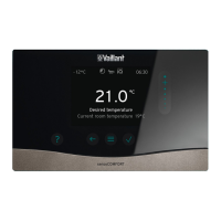
3.8 Data plate
The data plate is located on the rear of the system control
underneath the unit mounting bracket.
The data plate contains the following information:
Information on the identific-
ation plate
Meaning
Serial number for identification; 7th to
16th digits = product article
number
VRC 700f/4 Product designation
V Operating voltage
mA Current consumption
Read the instructions
LR06 Battery type designation
T60 Max. permitted environmental
temperature: 0 to 60 °C
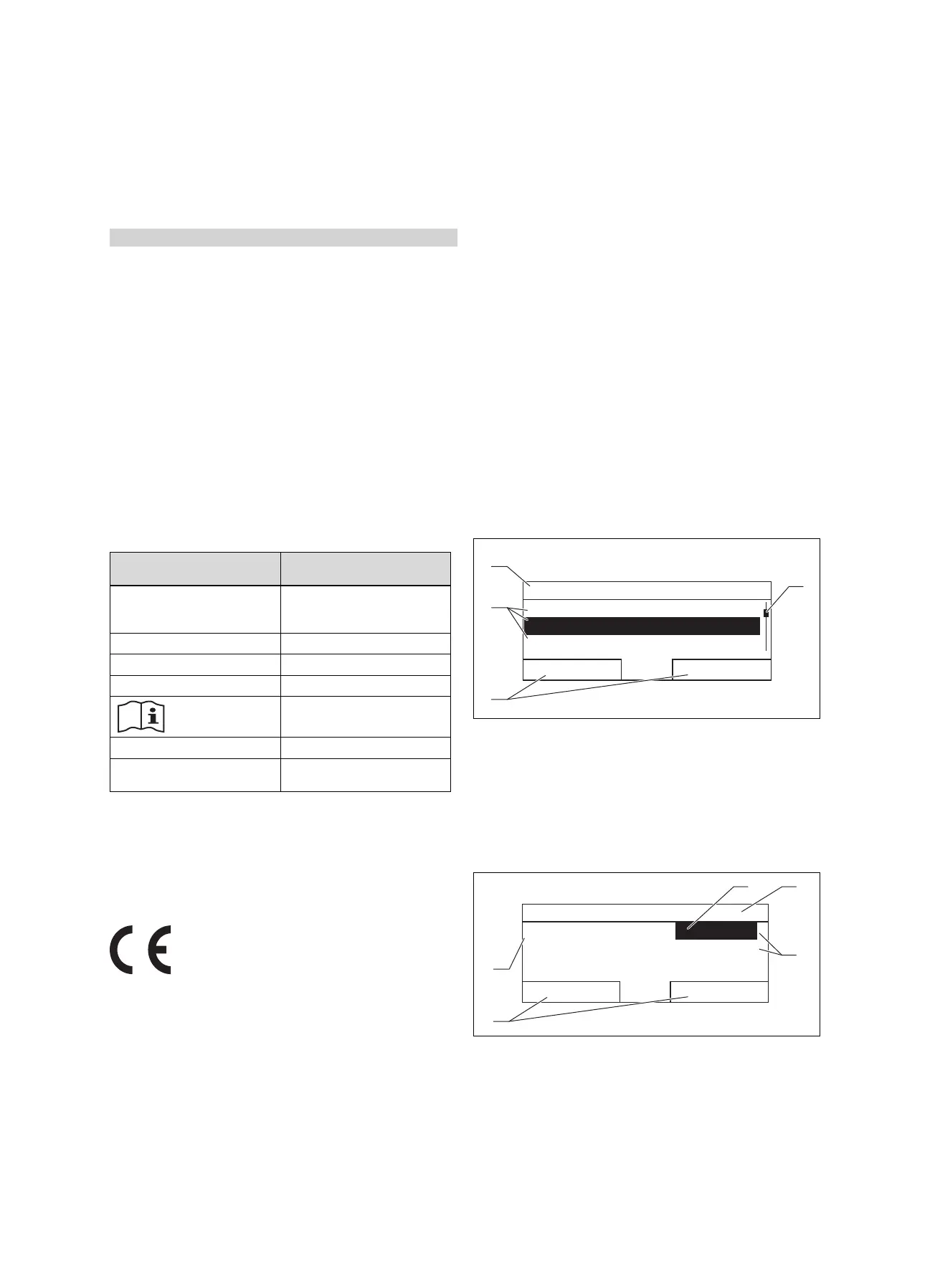
3.9 Serial number
You can call up the serial number to the display under Menu
→ Information → Serial number. The 10-digit article number
is located in the second line.
3.10 CE marking
The CE mark shows that the products comply with the basic
requirements of the applicable guidelines as stated on the
data plate.
The manufacturer hereby declares that the type of radio
equipment that is described in these instructions complies
with Directive 2014/53/EU. The complete text for the EU De-
claration of Conformity is available at: http://www.vaillant-
group.com/doc/doc-radio-equipment-directive/.
4 Operation
4.1 Operating structure
4.1.1 Adjustment and display levels
The product has two adjustment and display levels.
The end user level contains information and setting options
that you require as the end user.
The installer level is reserved for the competent person. It is
protected by a code. Only competent persons may change
any settings in the installer level.
End user level (→ Page 22)
4.1.2 Menu structure design
The menu structure consists of several selection levels and a
setting level.
You can always use the selection button Menu to access
selection level 1 from the basic display.
You can use the selection button Op. mode to directly ac-
cess the setting level Operating mode.
The lowest level is always the setting level.
4.1.3 Selection level
Menu
Information
Desired temperatures
Timer programmes
Back
Select
1
4
3
2
1 Scroll bar
2 Current functions of the
selection buttons
3 Selection level list
entries
4 Current function or
selection level
The scroll bar (1) only appears if there are more list entries
than can be shown at once on the display.
4.1.4 Setting level
Zone 1
Set-back temp. heat.Set-back temp. heat.
Day temp. coolingDay temp. cooling
Day temp. heatingDay temp. heating
Back
Change
20.0 °C20.0 °C
26.0 °C26.0 °C
15.0 °C15.0 °C
21
3
5
4
1 Current selection
2 Current selection level
3 Values
4 Current functions of the
selection buttons
5 Setting level
In the setting level, you can select the values you want to
read or change.
 Loading...