8 Operating and installation instructions 0020288151_04
2.12 Setting the heat curve
A
B
15 10 5 0 -5 -10 -15 -20
20
30
40
50
60
70
80
90
1.2
1.5
1.822.533.54
0.8
1.0
0.4
0.2
0.1
0.6
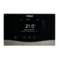
A Outside temperature °C B Target flow temperature
°C
The figure shows the possible heat curves of 0.1 to 4.0 for a
target room temperature of 20 °C. If, for example, heat curve
0.4 is selected, a flow temperature of 40 °C is maintained at
an outdoor temperature of -15 °C.
A
B
CD
18
22
20
0.4
70
60
50
40
30
15 10 5 0 -5 -10 -15 -20
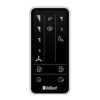
A Outdoor temperature °C
B Target flow temperature
°C
C Target room temperat-
ure °C
D Axis a
If the heat curve 0.4 is selected and 21 °C is specified for the
target room temperature, the heat curve is then translated,
as shown in the figure. The heat curve is displaced accord-
ing to the value of the target room temperature along axis a
which is angled at 45°. At an outdoor temperature of -15 °C,
the control system provides a flow temperature of 45 °C.
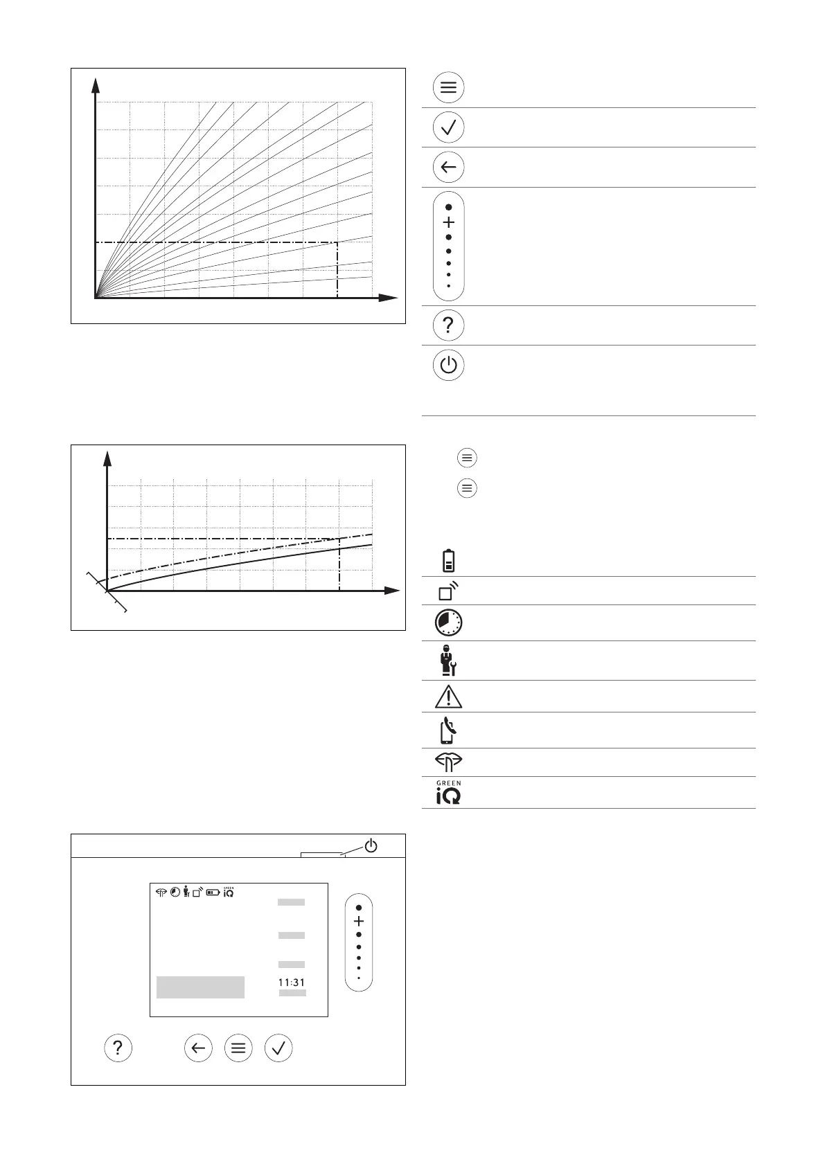
2.13 Display, control elements and symbols
2.13.1 Control elements
– Calling up the menu
– Back to the main menu
– Confirming a selection/change
– Saving set values
– One level back
– Cancelling input
– Navigating through the menu structure
– Reducing or increasing the set value
– Navigating to individual numbers/letters
– Calling up help
– Calling up the time programme assistant
– Switching on the display
– Switching off the display
The control element is located on the upper side of
the control.
Active control elements light up green.
Press once: You access the basic display.
Press twice: You access the menu.
2.13.2 Symbols
Battery state of charge
Signal strength
Time-controlled heating active
Maintenance required
Fault in the heating installation
Contact the competent person
Noise reduction mode active
Most energy-efficient heating mode active
 Loading...