4 System installation instructions 0020292325_01
2 Notes on the documentation
2.1 Observing other applicable documents
▶ Always observe all the operating and installation instruc-
tions included with the system components.
2.2 Working with the system assistant
The system assistant is used to help with the system installa-
tion and start-up. The important steps are shown, depending
on the selected basic system diagrams. All other necessary
instructions and information are described in the instructions
for the system components.
▶ Use the references to the instructions.
▶ Follow the information, directions and instructions that
are described here.
The settings on the control for the indoor unit and/or the
system control refer to the basic system diagram that was
shown before.
▶ Configure the system in accordance with the end user's
requirements.
▶ Adjust the system settings to the local conditions.
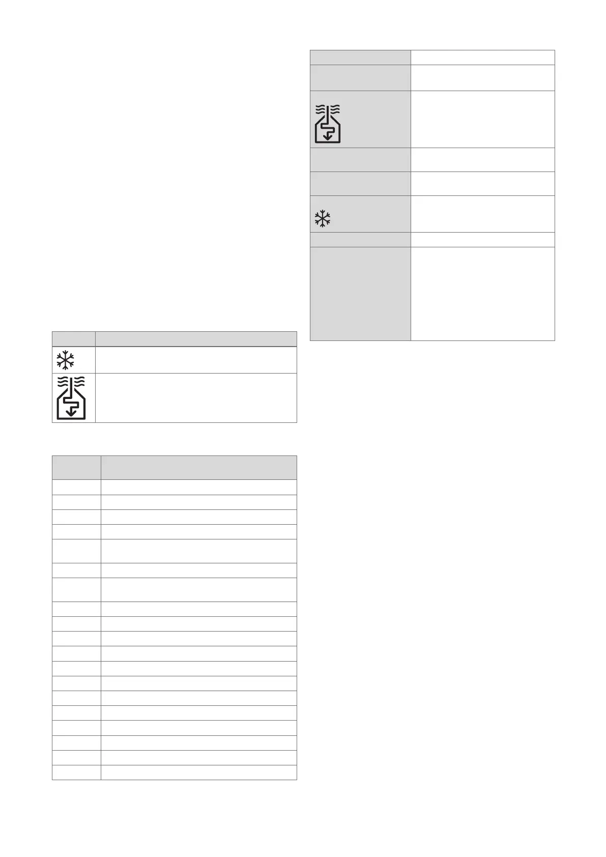
2.3 Key for the symbols
Symbol Meaning
Cooling
Air heat source
2.4 Key for the system components
Compon-
ent
Meaning
1 Heat generator
2a Air-to-water heat pump
7f Heat recovery module
8a Expansion relief valve
8c Safety assembly for the potable water connec-
tion
8e Expansion vessel for heating
9a Single-room temperature control valve
(thermostatic/motorised)
9d Bypass valve
9h Filling/draining cock
9j Tamper-proof capped valve
10e Line strainer with magnetite separator
10 l Flexible connections
12 System control
12b Heat pump expansion module
12g eBus coupler
12k Limit thermostat
12m Outdoor temperature sensor
12q VR 921 communication unit
SysFlow System temperature sensor
2.5 Mono heat pump systems
Basic system diagram 0020194193
Heat generator aroTHERM VWL ... A ... S2
VWZ AI
Heat source X
Regulated heating cir-
cuits
–
Non-regulated heating
circuits
1
Additional functions X
System control X
Special equipment From sensoCOMFORT VRC 720 or
multiMATIC VRC 700
ecoTEC VCW combi wall-hung boiler
VWZ MPS 40 heat recovery module
As of the VR 920 communication
unit
Outdoor temperature sensor
VR 32 bus coupler

 Loading...